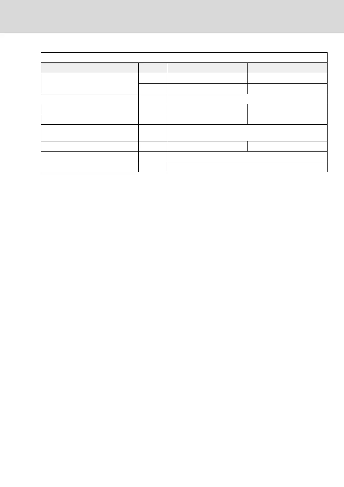
Spring terminal (connector) Unit Min. Max.
Connection cable
Stranded wire
mm
2
0,25 1,5
AWG 24 16
Stripped length mm 10
Current carrying capacity of outputs X6 A - 1,25
Time constant of load ms - 50
Number of switching operations at maxi‐
mum time constant of load
Wear-free electronic contact
Switching frequency Hz - 0,5
Short circuit protection X6.3 against X6.4 (output for controlling the motor holding brake)
Overload protection X6.3 against X6.4 (output for controlling the motor holding brake)
Tab. 6-9: Function, pin assignment
Motor holding brake: selection
Maximum current carrying capacity of outputs X6: 1.25 A
⇒ R
br (min)
= U
br (max)
/ 1.25 A
R
br (min)
: Minimum allowed resistance of the motor holding brake
U
br (max)
: Maximum supply voltage of the motor holding brake
If U
br (max)
= 24 V +5% = 25.2 V, this results in:
R
br (min)
= 20.16 Ω (applicable to all operating and ambient conditions)
Motor holding brake: installation
instructions
Make sure the power supply for the motor holding brake at the motor is suffi‐
cient. You have to take into account that voltage drops on the supply line.
Use connection lines with the highest possible cross section of the single
strands.
Use an external contact element in accordance with the required safety cate‐
gory, if you wish to supply motor holding brakes with higher currents than the
allowed current load at X6. Make sure to comply with the required minimum
current consumption of 100 mA when using the external contact element.
Otherwise, the brake current monitoring unit signals an error.
DOK-INDRV*-HCS01******-PR05-EN-P Bosch Rexroth AG 139/341
Rexroth IndraDrive CsDrive Systems with HCS01
Mounting and installation
 Loading...


