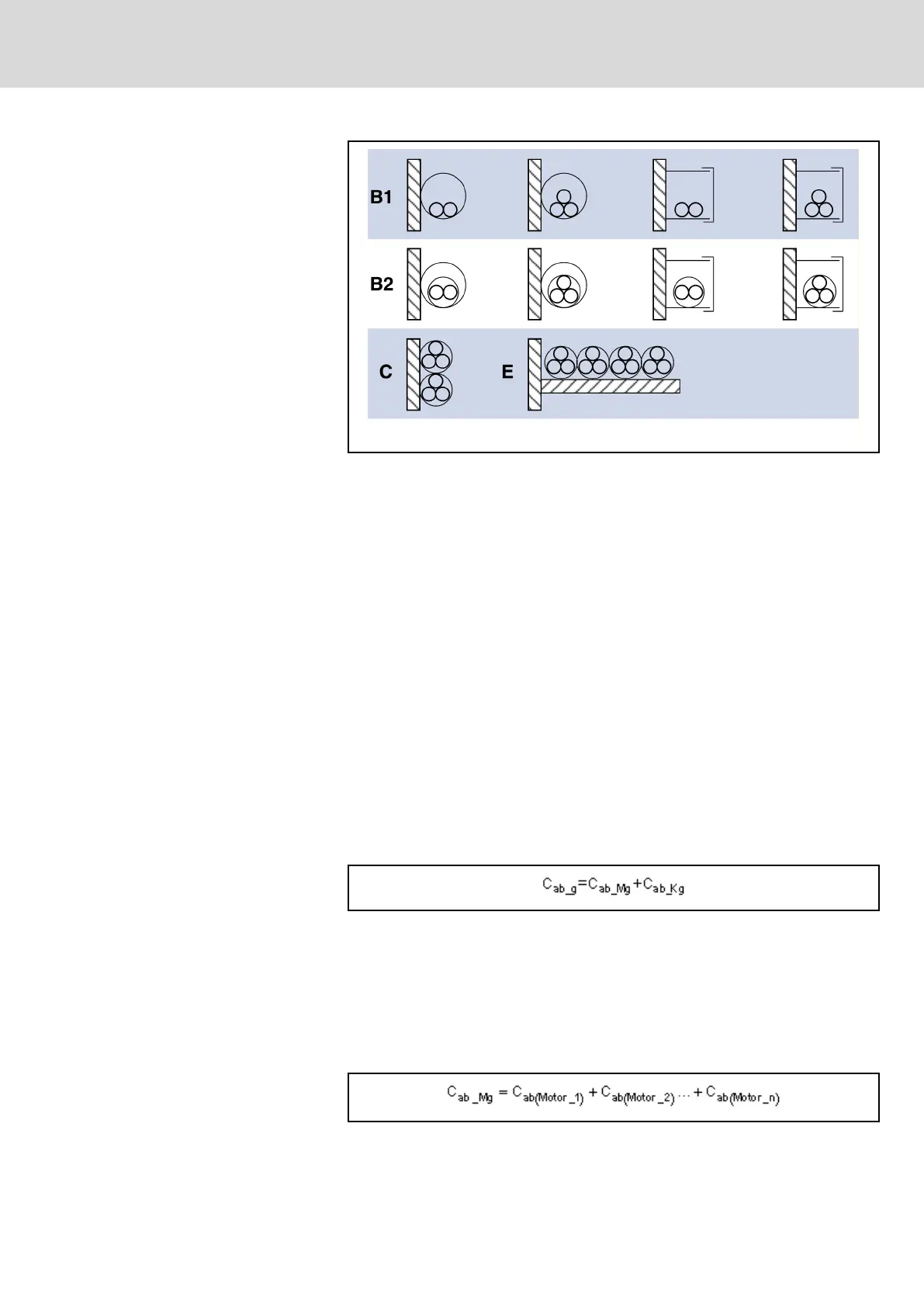
B1 Conductor in installation pipes and in installation channels to
be opened
B2 Cables or lines in installation pipes and in installation channels
to be opened
C Cables or lines on walls
E Cables or lines on open cable trays.
Fig. 11-1: Installation methods (compare IEC 60364-5-52; VDE0298-7; EN
60204-1)
11.2 Determining the Leakage Capacitance
The capacitances which generate so-called leakage currents against ground
at the outputs of inverters are regarded as leakage capacitance C
ab
. The de‐
cisive values for the total value C
ab_g
of the leakage capacitance are:
● Capacitances of output filters
● Capacitances of power cables (capacitance per unit length against
shield and ground wire)
● Capacitances of motors (winding capacitance against housing)
The leakage capacitance consists of the values of power cable and motor of
all individual drives operated at the mains filter.
Calculation:
C
ab_g
Total value of leakage capacitance
C
ab_Mg
Total value of leakage capacitance of motor
C
ab_Kg
Total value of leakage capacitance of cable
Fig. 11-2: Total Leakage Capacitance
The total capacitance C
_ab_Mg
results from the sum of capacitances of the in‐
dividual motors. For these individual capacitances, see documentation of the
motor. For a list of selected values, see Appendix of this documentation un‐
der chapter 11.3 "Leakage Capacitances" on page 326.
C
ab(motor)
Leakage capacitance of a motor
Fig. 11-3: Total Leakage Capacitance of Motor
DOK-INDRV*-HCS01******-PR05-EN-P Bosch Rexroth AG 325/341
Rexroth IndraDrive CsDrive Systems with HCS01
Appendix
 Loading...


