FRU Disassembly 8-19
Upper Transportation and Registration
Paper Size Switches
Both paper size sensing switch arrays are located behind the AC Accessory Panel.
Use this procedure to replace either the Tray 2 or Tray 3 Paper Size switches.
Note
To remove the Tray 2 switch, remove the Engine Logic Board (page 8-89), and
loosen the Engine Logic Board Bracket.
1. Remove the I/P Board Cover (page 8-14).
2. Remove the Upper Rear Cover (page 8-15).
3. Remove the Lower Rear Cover (page 8-16).
PL2.1.4
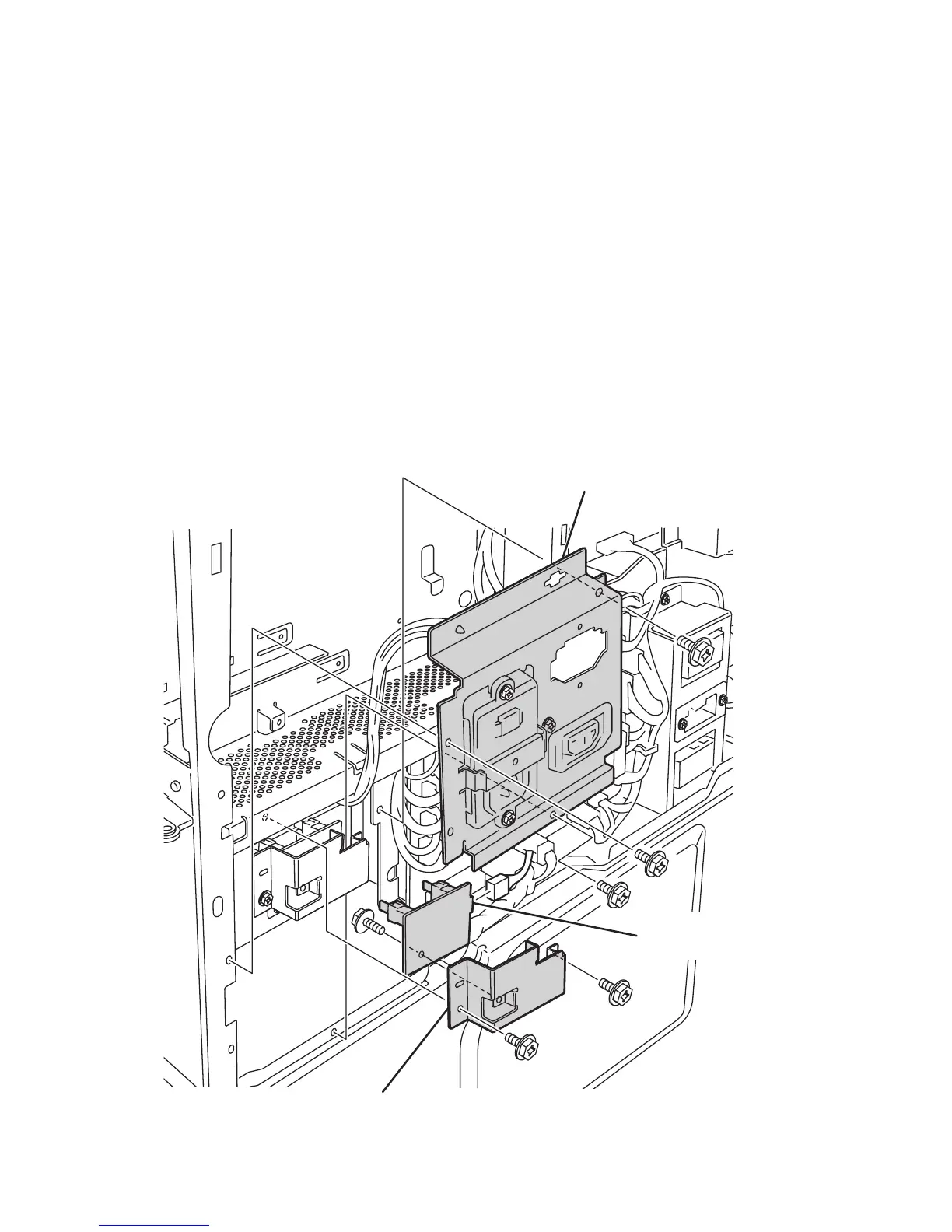
4. Remove the three screws securing the AC Accessory Panel.
AC Accessory Panel
Paper Size Switch
Switch Bracket
s5500-092

 Loading...


