8-92 Phaser 5500 Printer Service Manual
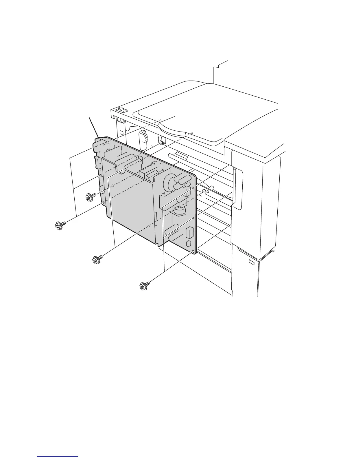
Low Voltage Power Supply
1. Remove the Upper Right Cover (page 8-11).
PL8.1.8
2. Mark and disconnect all connectors from the LVPS. Connectors P1, P2, P6, P521
and P526 have a hook. Disconnect by pushing the hook.
3. Remove the nine screws securing the LVPS to the frame.
4. Remove the LVPS.
Replacement Note
Fit the holes on the board to the two bosses on the frame. P7 is unused.
Caution
J11 (Black wire), J12 (White wire) are interchangeable. Use the designators
printed on the board to identify the proper connection.
s5500-186
LVPS

 Loading...


