FRU Disassembly 8-91
Image Processor Board
1. Remove the I/P Board Cover (page 8-14).
2. Disconnect all external interface connections.
PL8.1.5
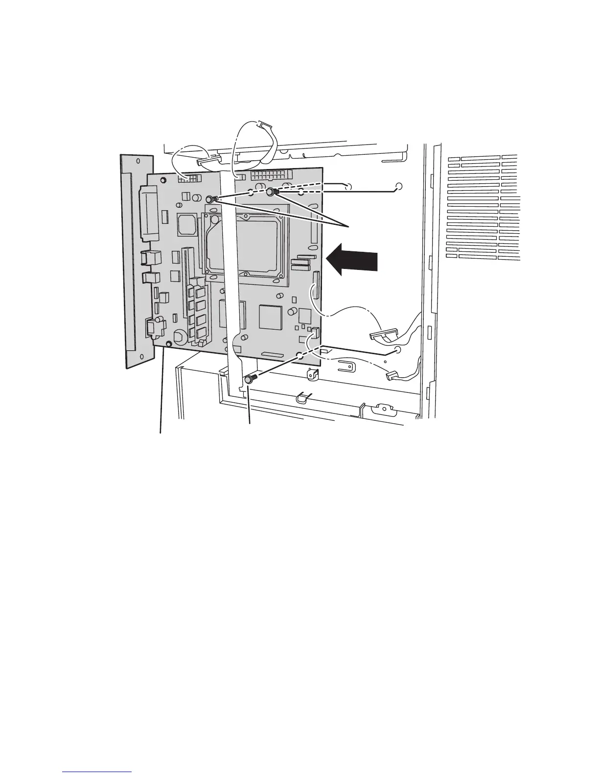
3. Disconnect the four connectors from the I/P Board.
4. Remove the three 5.5mm, hex-head screws securing the I/P Board to the frame.
5. Remove the I/P Board and its carrier using the knob provided on the rear panel.
Replacement Note
Tighten the back panel screw before tightening the board mounting screws.
If installing a new I/P Board, be sure to transfer NVRAM, Configuration
Card, and if installed, the Flash Memory and Hard Drive to the new board.
s5500-61
Image Processor Board
Screw
Screws

 Loading...


