Theory of Operation 2-27
Trays 2 and 3
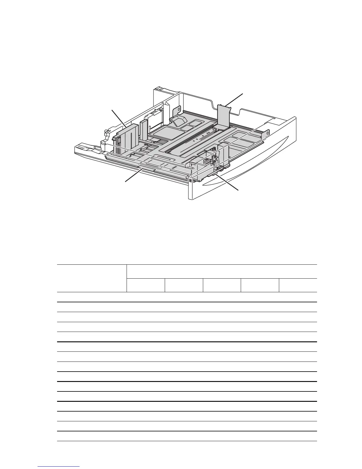
The universal trays 2 and 3 include end and side guides that manually adjust to the
paper loaded in the tray. These guides come into contact with the front and rear edges
of the paper and hold it in position. Paper size is determined by the position of the
switches in the Paper Size Switch assembly. The signal created by these switches
indicates the paper size setting of the guides.
The following table provides the switch states corresponding to the pre-defined paper
sizes. The switches are denoted by “SW1”, “SW2”, “SW3”, SW4 and “SW5”,
respectively, when viewed from the left side.
Universal Tray Paper Size Switch Signal States
Paper size
Paper Size Switch Output
SW1 SW2 SW3 SW4 SW5
No tray 0 0 0 0 0
5.5" x 8.5" / A5 SEF 0 0 1 0 0
B5 SEF 0 0 1 1 1
8.5" x 13" SEF 0 1 0 1 0
8.5" x 14" SEF 0 1 0 1 1
A4 SEF 0 1 1 0 0
8.5" x 11" SEF 0 1 1 0 1
A4 LEF 1 0 1 0 0
A3 SEF 1 0 1 1 0
B5 LEF/Executive LEF 1 1 0 0 1
8K SEF(TFX/GCO) 1 1 0 1 0
B4 SEF 1 1 0 1 1
8.5" x 11"LEF 1 1 1 0 0
16K LEF(TFX/GCO) 1 1 1 0 1
11" x 17"LEF 1 1 1 1 1
End Guide
Front Side Guide
Bottom Plate
Rear Side Guide
s5500-033

 Loading...


