Garmin G1000 Pilot’s Guide for the Diamond DA42NG
190-00962-02 Rev. A
48
FLIGHT INSTRUMENTS
SYSTEM
OVERVIEW
FLIGHT
INSTRUMENTS
EIS
AUDIO PANEL
& CNS
FLIGHT
MANAGEMENT
HAZARD
AVOIDANCE
AFCS
ADDITIONAL
FEATURES
APPENDICESINDEX
2.1 FLIGHT INSTRUMENTS
AIRSPEED INDICATOR
NOTE: Refer to the Aircraft Flight Manual (AFM) for airspeed criteria and Vspeed values.
The Airspeed Indicator displays airspeed on a moving tape rolling number gauge. The true airspeed is
displayedinknotsbelowtheAirspeedIndicator.Thenumericlabelsandmajortickmarksonthemoving
tapeareshownatintervalsof10knots.Theminortickmarksonthemovingtapearemarkedatintervalsof
veknots.Speedindicationstartsat20knots,with60knotsofairspeedviewableatanytime.Theindicated
airspeedisdisplayedinsidetheblackpointer.Thepointerremainsblackuntilreachingnever-exceedspeed
(V
NE
), at which point it turns red.
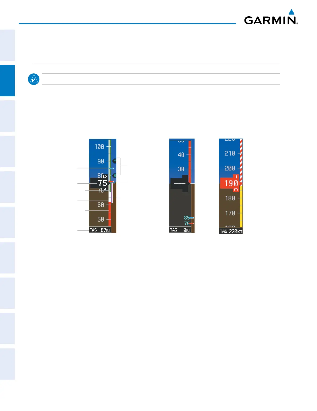
Figure 2-3 Airspeed Indicator Ranges
Red and White
Barber Pole at V
NE
Low Speed Range
Speed
Ranges
Indicated
Airspeed
True
Airspeed
Airspeed Indicator
Operating Ranges
Airspeed
Trend Vector
V
YSE
V
MCA
Vspeed
References
ColorcodedstripesappearontheAirspeedIndicatortoshowtheoperatingranges.Thelowspeedrange
stripeisred.Normaloperatingrangeisgreen,cautionrangeisyellow,andtheneverexceedspeed(V
NE
) begins
with a red and white barber pole. The flap operating range is indicated by a white stripe.
TheAirspeedTrendVectorisaverticalmagentalinethatappearstotherightofthecolor-codedspeedrange
stripwhenairspeed is either accelerating or decelerating. Oneendofthe magenta line is anchoredtothe
tip of the airspeed pointer while the other end moves continuously up or down corresponding to the rate of
acceleration or deceleration. For any constant rate of acceleration or deceleration, the moving end of the line
shows approximately what the indicated airspeed value will be in six seconds. The trend vector is absent if the
speed remains constant or if any data needed to calculate airspeed is not available due to a system failure.

 Loading...


