Revision C CASE 6-9
2060290-201
Before the Test
Before the Test
Pre-Acquisition Screen
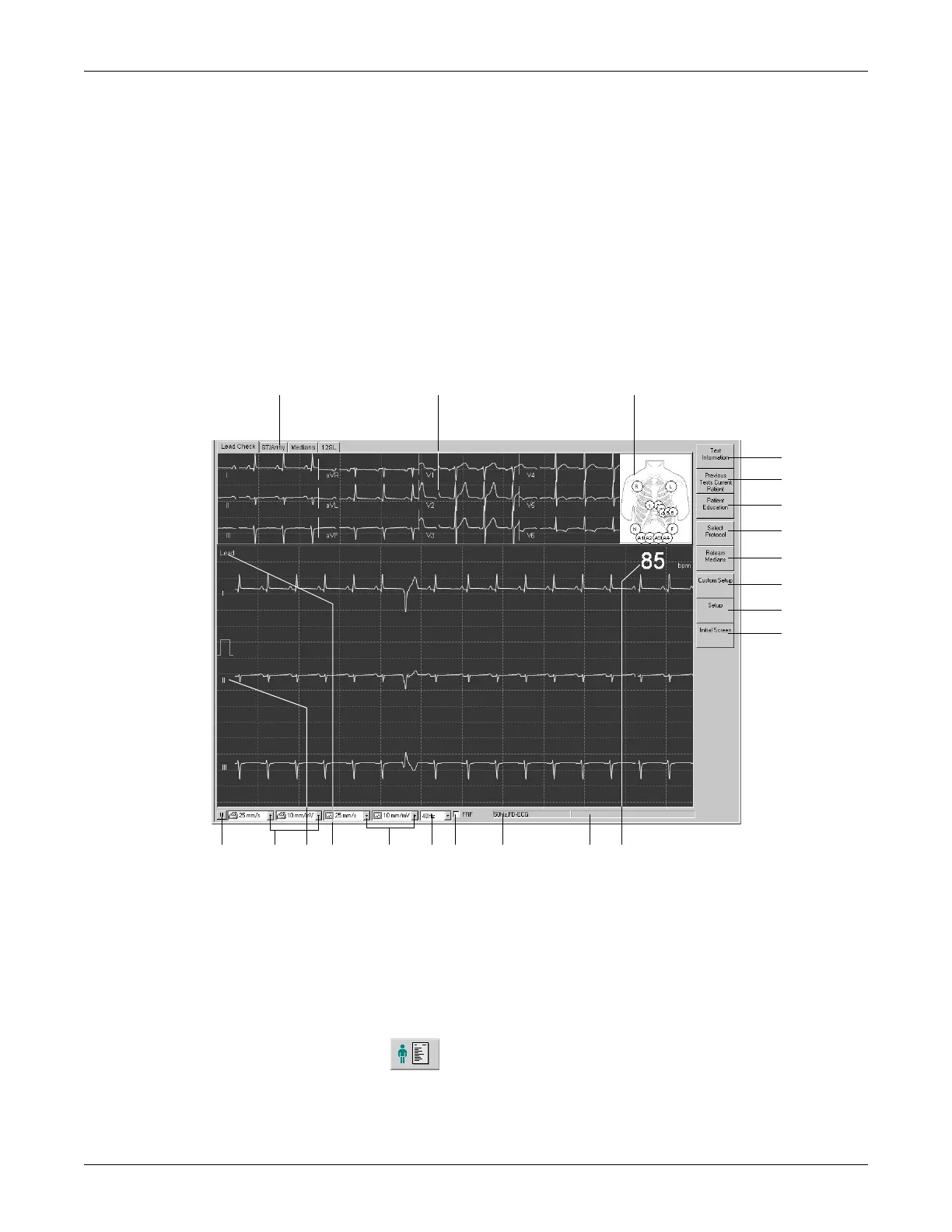
Overview
In the upper part of the screen you see the lead check information for
verification of the ECG signal quality. All 12 or 15 leads are shown. The
schematic lead check torso allows you to verify the applied electrodes.
The actual waveform data appears in the area below.
056A-S
B
S
D
A C
E
F
G
H
J
I
K
LMOPQRTU N
A Tabs showing the different ECG analysis data.
B Lead check status window (other tabs are explained in "During the Test"
on page 6-18 (ST/Arrhy), 6-19 (Medians) and 6-25 (12SL).
C Schematic representation of the applied electrodes:
green: correct, yellow: lead problem (high impedance), white: not used,
red: electrode disconnected or lead break (numbers indicate the
impedance value in kΩ).
D Click to enter or review test information.
 Loading...


