GE HEALTHCARE
DIRECTION 2286865, REVISION 14 LOGIQ™ 7 SERVICE MANUAL
5-42 Section 5-7 - Air Flow Control
Section 5-7
Air Flow Control
5-7-1 Air Flow Distribution
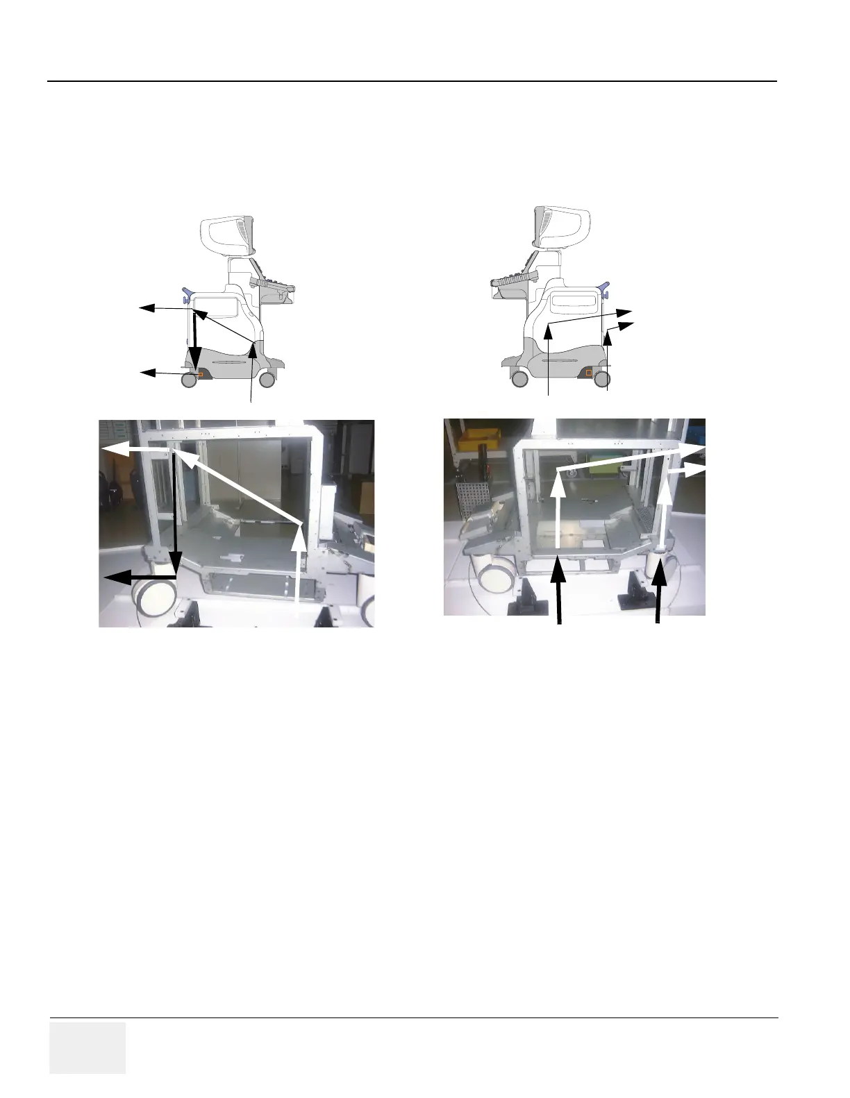
The four air flow pathes allow the scanner to be cooled down as shown in the figure above.
• Path A (Front lower left > Filter > PC Box > Rear upper left) for PC Box cooling.
• Path B (Front lower left > Filter > LV unit > Rear lower left) for LV unit cooling.
• Path C (Bottom right > Filter > NEST Assy > Rear upper right) for NEST Assy cooling.
• Path D (Rear bottom right > Filter > HV unit > Rear upper right) for HV unit cooling.
5-7-2 Filters
The scanner contains the three filters located at:
- Front lower left for air flow of the LV unit and PC box.
- Bottom right for air flow of the NEST Assy.
- Rear bottom right for air flow of the HV unit.
Figure 5-67 Air Flow Inside the Scanner
A
B
C
D
A
B
C
D

 Loading...


