GE HEALTHCARE
DIRECTION 2286865, REVISION 14 LOGIQ™ 7 SERVICE MANUAL
3-14 Section 3-4 - Completing the Installation
3-4-2-1 Approved on-board peripherals (cont’d)
Connecting Cables
3-4-2-2 Reference off-board peripherals and options
None.
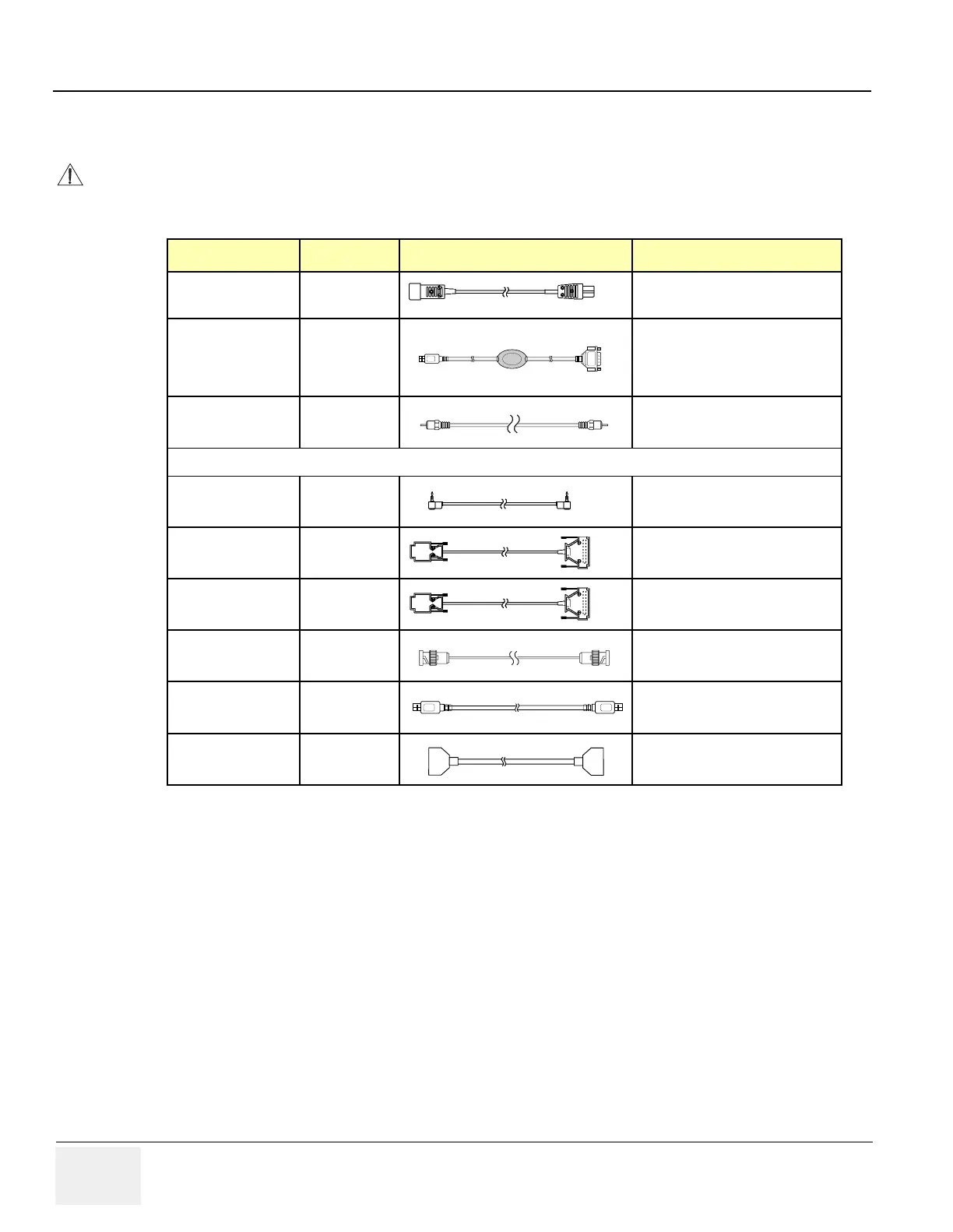
CAUTION
Equipment damage possibility. Be sure to use the following recommended connecting cables to connect
recording devices and a network with LOGIQ™ 7 console.
Table 3-4 List of Connecting Cables
Name Part No. Figure NOTE
Power Supply Cable P9509EE
Connected to power
USB Serial Bridge
Cable
2304621
For converting the signal of
RS232C cable to USB cable:
connected to VCR1 on the Rear
Panel
AV Cable 2119874
Connected to Video-In/Out on the
Rear Panel
The followings are the cables for BT04 ore lower system ONLY.
Mini-Plug Cable P9509BE
Shutter control signals:
connected to B/W Printer
RS232C Cable
Cross
2305550
For control signals:
connected to Serial Bridge Cable
RS232C Cable
Straight
2305549
For control signals:
connected to Serial Bridge Cable
BNC Cable 2297053
For control signal:
connected to Composite B/W
USB Cable 2324360
Connected to USB port.
SCSI cables
(UP-D50 ONLY)
2375479
Connected toSCSI port and SCSI
Cable Connector.

 Loading...


