GE HEALTHCARE
DIRECTION 2286865, REVISION 14 LOGIQ™ 7 SERVICE MANUAL
Section 6-8 - Jumper and Dip Switch Setting 6-37
Section 6-8
Jumper and Dip Switch Setting
6-8-1 Dip Switch Setting
Normally the dip switches shall not be adjusted. In case of special needs, such as scanner upgrade,
refer to each instructions/documentations for proper setting.
The dip switch must be set properly according to the table below. The value in the table (Dip Switch
setting) represents the bit location as shown.
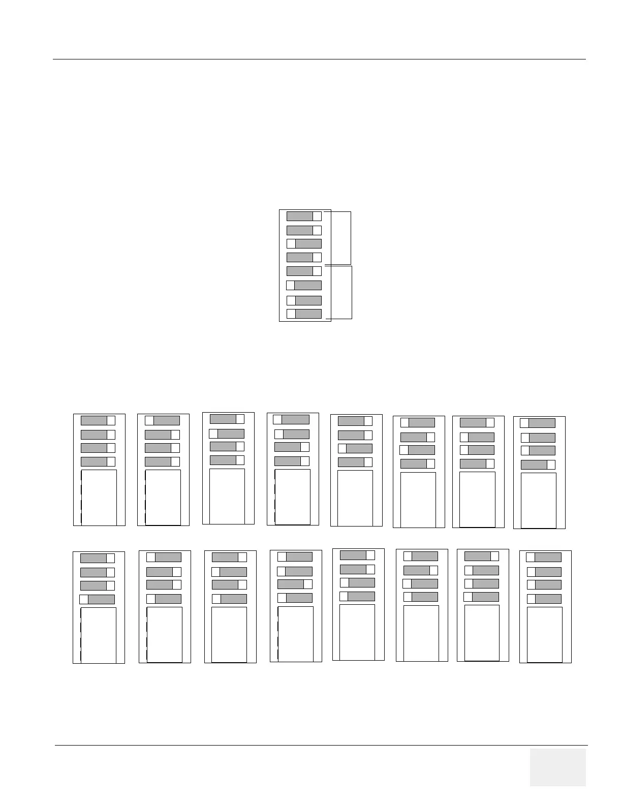
Figure 6-47 Dip Switch Setting
Figure 6-48 Bit Setting (1 to 4)
4 (lower 4 bits)
E (Upper 4 bits)
Example: “E4 (h)” is set as shown.
O
N
1
2
3
4
5
6
7
8
O
N
1
2
3
4
5
6
7
8
O
N
1
2
3
4
5
6
7
8
O
N
1
2
3
4
5
6
7
8
O
N
1
2
3
4
5
6
7
8
O
N
1
2
3
4
5
6
7
8
O
N
1
2
3
4
5
6
7
8
O
N
1
2
3
4
5
6
7
8
O
N
1
2
3
4
5
6
7
8
0 (h) 1 (h) 2 (h) 3 (h) 4 (h) 5 (h) 6 (h) 7 (h)
O
N
1
2
3
4
5
6
7
8
O
N
1
2
3
4
5
6
7
8
O
N
1
2
3
4
5
6
7
8
O
N
1
2
3
4
5
6
7
8
O
N
1
2
3
4
5
6
7
8
O
N
1
2
3
4
5
6
7
8
O
N
1
2
3
4
5
6
7
8
O
N
1
2
3
4
5
6
7
8
8 (h) 9 (h) A (h) B (h) C (h) D (h) E (h) F (h)
Bit Setting for DIP Switch 1 to 4 (lower 4 bits)

 Loading...


