GE HEALTHCARE
DIRECTION 2286865, REVISION 14 LOGIQ™ 7 SERVICE MANUAL
Section 3-5 - Installation Paperwork 3-19
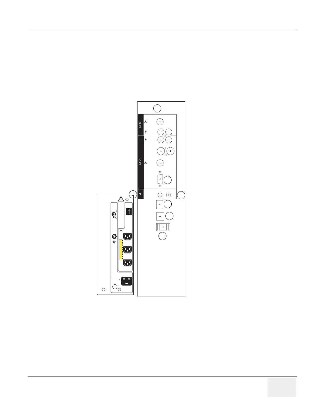
3-5-1-1 Rear Panel Connector
Located on the rear panel are video input and output connectors, audio input and output, camera
expose connectors, footswitch connector power connector and control connections for VCR, printer,
and service tools.
This section indicates the pin assignment for each connector.
Figure 3-7 Rear Pannel Connector (BT04 or later)
Video In
Re
c/
Expose
VGA
S-Video
Out
S-Video
In
Cmpst
Out
Insite
Audio
In
LR
LR
Audio
Out
Ethernet
VCR2 VCR1 Service
Camera
B/WColor
B/WColor
Video Out
Power
AC Line Input
1200VA
220
-
240V
Circuit
Breaker
Circuit
Breaker
50/ 60Hz
Power
AC Line Input
1200VA
50/ 60Hz
100
-
120V
Circuit
Breaker
Circuit
Breaker
100-120V 350VA Max
Rear Pannel Connector for BT04 and later models
5
6
8
7
2
3
1

 Loading...


