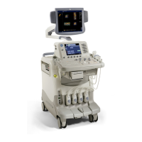

Do you have a question about the GE LOGIQ 7 and is the answer not in the manual?
| Power Supply | 100-240 VAC, 50/60 Hz |
|---|---|
| Type | Ultrasound System |
| Application | General Imaging, Vascular |
| Imaging Modes | B-mode, M-mode, Color Doppler, Power Doppler |
| Advanced Features | SRI (Speckle Reduction Imaging), CrossXBeam (Spatial Compounding) |
| Probes | Convex, Linear, Phased Array, Endocavitary |
| Connectivity | DICOM, Ethernet |
Provides an overview of the manual's content, including purpose, chapter contents, and service manual purpose.
Details conventions used in the book, including icons, safety precaution messages, and model designations.
Covers crucial safety aspects for operating personnel and equipment handling, including human, mechanical, and electrical safety.
Addresses Electromagnetic Compatibility, Electromagnetic Interference, Electrostatic Discharge prevention, and CE Compliance requirements.
Provides information on system manufacture and contact details for customer support and service.
Details the purpose of the chapter, outlining facility and electrical needs for installation planning.
Specifies environmental and electrical requirements for the console, including power, cooling, and lighting.
Outlines purchaser responsibilities, required features, and desirable ultrasound room facilities for proper installation.
Provides an overview of the installation process, including procedures for receiving, unpacking, and preparing the unit.
Details the procedures for receiving and unpacking the system, including checking for shipping damage and shortages.
Covers essential preparation steps before installation, such as verifying customer orders, physical inspection, and EMI protection.
Guides through the final steps of installation, including probe connection, peripheral setup, and available probes.
Details the documentation and connector panel information required for installation completion.
Introduces the chapter's purpose, which is to provide procedures for checking major system functions and diagnostics.
Outlines general procedures for system operation, including lockout/tagout, power on/boot up, and maintenance mode entry.
Covers functional checks for system modes, basic measurements, and probe elements to ensure proper operation.
Provides information on accessing and using diagnostic tools, including service software, test menus, and utilities.
Details the site log for recording maintenance activities, problems, and comments.
Explains system concepts, component arrangement, subsystem functions, PDS, and probes.
Provides a detailed matrix of hardware compatibility across different system versions and FRUs.
Explains system block diagrams and theoretical functions, including CPU/Back End Processor details.
Describes the Common Service Platform, its user interface, internationalization, and service login procedures.
Details air flow distribution, filters, and fan locations within the scanner for optimal cooling.
Introduces the chapter on testing and adjusting the scanner, noting that tests are optional.
Details procedures for accessing and adjusting LV unit DC output voltages.
Explains how to adjust the front and rear brake lock adjusters and swivel lock.
Provides procedures for adjusting CRT and LCD monitor contrast, brightness, resolution, and touch panel.
Details the procedure for cleaning the trackball and its housing, including safe handling practices.
Describes the proper setting for dip switches and jumpers, noting they should not be adjusted unless necessary.
Provides an overview of diagnostic procedures for maintaining image quality and system operation.
Outlines the diagnostic framework, levels (board/system), and logical step-by-step approach for check-out and fault isolation.
Introduces replacement procedures for modules and subsystems, and guidelines for returning parts.
Details software loading procedures, work-flow, check-lists, and system settings for BT09.
Provides an overview of renewal parts for LOGIQ™ 7 systems.
Lists renewal parts for BT09 system FRUs, including equipment models covered.
Details renewal parts for R7.5.x system FRUs, covering equipment models.
Provides renewal parts lists for BT07 system FRUs, categorized by CRT, LCD, and PRO models.
Lists renewal parts for V65x system FRUs, covering CRT and LCD models.
Details renewal parts for BT06-2 or later systems, covering CRT, LCD, and PRO models.
Lists renewal parts for BT06-2 CONSIP (SOI) systems, covering equipment models.
Provides renewal parts lists for BT04 and BT06 systems, covering CRT, LCD, PRO, and other models.
Lists renewal parts for BT03 or lower systems, covering various equipment models and components.
Provides an overview of Periodic Maintenance (PM) procedures for the scanner and peripherals.
Explains the importance of periodic and corrective maintenance, including keeping records and quality assurance.
Details the schedule for PMs and the frequency of services, emphasizing regular maintenance for performance.
Lists the tools required for standard GE tool kits, noting not all tools are needed for PMs.
Outlines preliminary checks, functional checks, peripheral/option checks, and cleaning procedures for system maintenance.
Covers electrical safety tests based on NFPA 99 and IEC 60601-1, including leakage current limits and testing procedures.