GE HEALTHCARE
DIRECTION 2286865, REVISION 14 LOGIQ™ 7 SERVICE MANUAL
Section 3-5 - Installation Paperwork 3-21
3-5-1-1 Rear Panel Connector (cont’d)
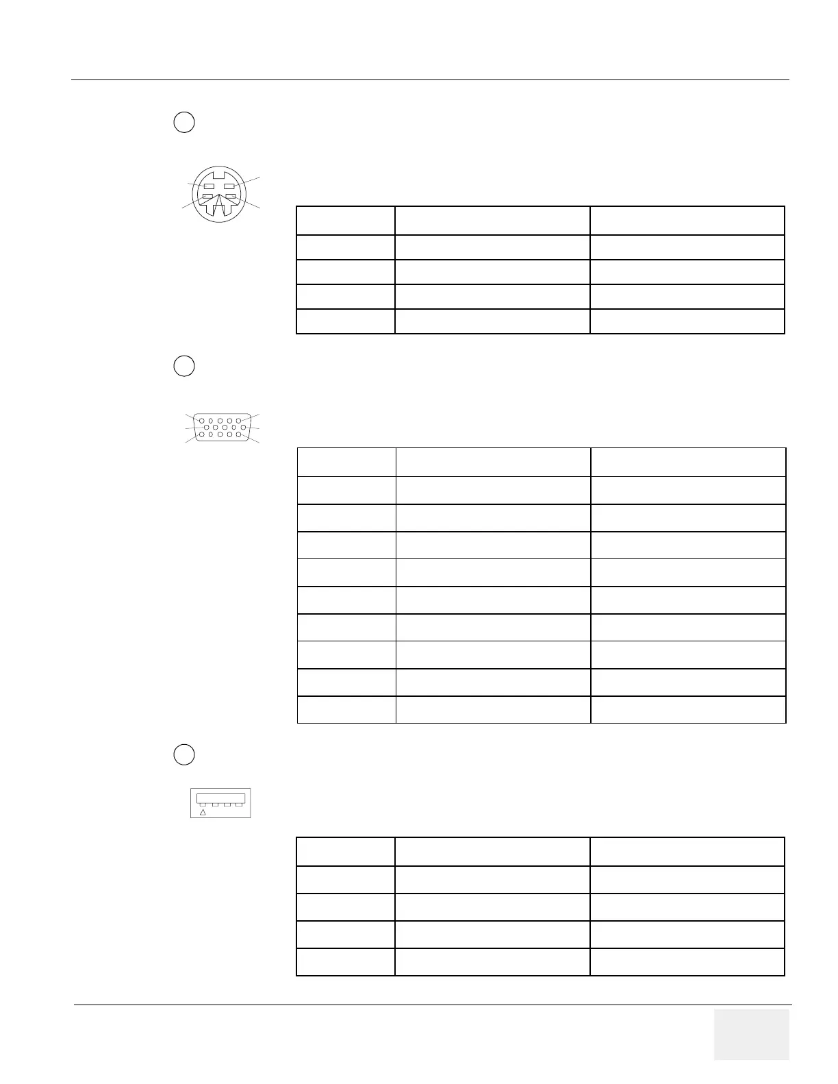
Pin Assignment of S-Video Connector
Connector: S-Terminal, 4-pin
Pin Assignment of VGA Connector
Connector: Shrank D-Sub, 15-pin
Pin Assignment of Service/VCR 1/VCR 2 Connector, USB1.1
Connector: 4 pin
Table 3-10 Pin Assignment of S-Video Connector
Pin No Output/Input Signal Description
1 SVIDEO OUT/IN YG Y (Luma) GND
2 SVIDEO OUT/IN CG C (Chroma) GND
3 SVIDEO OUT/IN Y Y (Luma) SIGNAL
4 SVIDEO OUT/IN C C (Chroma) SIGNAL
Table 3-11 Pin Assignment of VGA Connector
Pin No Output Signal Description
1 IO VGA OUT1 R Red
2 IO VGA OUT1 G Green
3 IO VGA OUT1 B Blue
6 IO VGA OUT1 RG Reg GND
7 IO VGA OUT1 GG Green GND
8 IO VGA OUT1 BG Blue GND
13 IO VGA OUT1 HS H Sync
14 IO VGA OUT1 VS V Sync
Others GND GND
Table 3-12 Pin Assignment of Service/VCR 1/VCR 2 Connector
Pin No Output Signal Description
1 VBUSn Power Supply
2 Dn Data (-)
3 Dn Data (+)
4 GNDn Power Ground
1
2
4
3
1
2
1
6
11
5
10
15
3
1 2 3 4

 Loading...


