Home
GE
Medical Equipment
LOGIQ 7
GE LOGIQ 7 Service Manual
4
of 1
of 1 rating
394 pages
Give review
Manual
Specs
To Next Page
To Next Page
To Previous Page
To Previous Page
Loading...
GE H
EALTHCARE
D
IRECTION
2286865, R
EVISION
14
LOGIQ™ 7 S
ERVICE
M
ANUAL
Secti
on 3-1 - Over
view
3-7
3-2-3
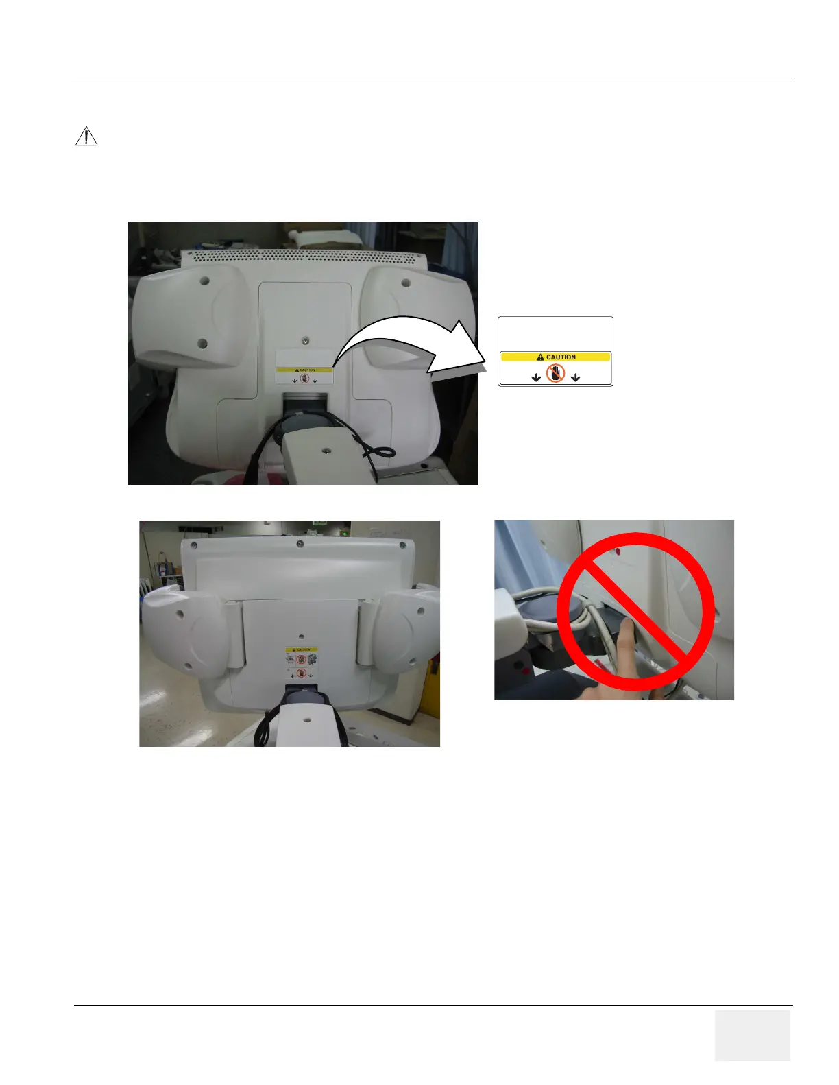
LCD Monitor Tilt Caution
CAUTION
Do NOT put your hand here! Your finge
rs might be pinched when adjusting angle of the LCD
monitor.
Figure 3-3 LCD Monitor Tilt Caution
For R7.5.
x 19inch LCD sys
tem
64
66
Table of Contents
Default Chapter
3
Important Precautions
3
Certified Electrical Contractor Statement
10
Damage in Transportation
10
Omissions & Errors
10
Legal Notes
11
Revision History
13
List of Effected Pages
14
Table of Contents
15
CHAPTER 1 Introduction
23
Introduction
23
Overview
23
Chapter Contents
23
LOGIQ 7 Model Designations
24
Typical Users of the Basic Service Manual
24
LOGIQ™ 7 Models Covered by this Manual
24
Purpose of Operator Manual(S)
26
Purpose of Service Manual
23
Important Conventions
27
Conventions Used in Book
27
Standard Hazard Icons
28
Standard Icons that Indicates that a Special Procedure Is to be Used
28
Product Icons
29
Warnings
29
Safety Considerations
32
Human Safety
32
Mechanical Safety
32
Introduction
32
Electrical Safety
33
Label Locations (for BT07 or Later, Including R7.5.X)
34
Label Locations (for BT04, BT06, and V65X)
36
Label Locations (for BT03 or Lower)
38
Dangerous Procedure Warnings
40
Lockout/Tagout Requirements (for USA Only)
40
Returning/Shipping Probes and Repair Parts
40
How to Remove the Ghost CD-ROM
41
Removing Bolts
42
Removing Ghost CD-ROM
42
EMC, EMI, and ESD
43
Electromagnetic Compatibility
43
Electrostatic Discharge (ESD) Prevention
43
CE Compliance
43
Customer Assistance
44
System Manufacture
44
Phone Numbers for Customer Assistance
44
Contact Information
44
CHAPTER 2 Pre Installation
47
Overview
47
Purpose of this Chapter 2
47
General Console Requirements
48
Console Environmental Requirements
48
Cooling
48
Environmental Requirements for an Ultrasound Room
48
Electrical Requirements
49
Inrush Current
49
LOGIQ 7 Power Requirements
49
Site Circuit Breaker
49
Power Stability Requirements
50
Site Power Outlets
50
Unit Power Plug
50
EMI Limitations
51
EMI Prevention/Abatement
51
Probes Environmental Requirements
52
Operation and Storage Temperatures for 2D Probes
52
Operation and Storage Temperatures for 4D Probes
52
Facility Needs
53
Purchaser Responsibilities
53
Required Features
54
Desirable Ultrasound Room Facilities
54
Recommended and Alternate Ultrasound Room Layout
55
DICOM Option Pre-Installation Requirements
56
Networking Pre-Installation Requirements
56
Purpose of DICOM Network Function
56
Average Installation Time
59
Overview
59
Purpose of Chapter 3
59
Installation Warnings
60
Brake Pedal Operation
60
Time for Settlement
60
Receiving and Unpacking the Equipment
61
Unpacking Procedures
61
Labels on Package
62
Safety Reminders
63
Moving into Position
64
LCD Monitor Tilt Caution
65
LCD Monitor Swing Cautionlcd Monitor Tilt Caution
66
LCD Monitor Removal Caution
67
Shipping Delivery Requirements
67
Preparing for Installation
68
Physical Inspection
68
System Voltage Settings
68
EMI Protection
68
Verify Customer Order
68
Completing the Installation
69
Probe (Transducer) Connection
69
Optional Peripherals/Peripheral Connection
70
How to Hold Peripherals
71
Connecting Cables
72
List of Connecting Cables
72
Available Probes
73
List of Transducers Supported (All Models)
73
List of Transducers Supported by BT09 and Later
74
List of Transducers Supported by R7.5.X and Later
74
List of Transducers Supported by V65X and Later
74
Video Specification
75
Software Option Configuration
75
Onsite Check and Configuration
75
Installation Paperwork
76
Peripherals/Accessories Connector Panel
76
Irection Evision Logiq™ 7 Service Anual
76
Rear Panel Connector
77
Rear Pannel Connector (BT04 or Later)
77
Rear Pannel Connector for BT04 and Later Models
77
Rear Panel Connector (BT03 or Lower)
78
Rear Pannel Connector for BT03 or Lower
78
Pin Assignment of S-Video Connector
79
Pin Assignment of Service/Vcr 1/VCR 2 Connector, USB1.1
79
Pin Assignment of VGA Connector
79
Pin Assignment of Digital Int. Connector
80
Pin Assignment of Ethernet
80
Pin Assignment of Insite
80
Front Connector Panel
81
Pin Assignment for Camera B/W
81
B/W Printer Connector Panel
82
Footswitch Connector Panel
82
CHAPTER 4 Functional Checks
85
Special Equipment Required
85
Overview
85
Purpose for Chapter 4
85
General Procedure
86
Lockout/Tagout Requirements
86
Power On/Boot up
86
Main Circuit Breaker
86
Power On/Off Standby Switch Location
87
Power up Sequence
87
Start up Screen
87
Entering Maintenance Mode
88
Clicking on Mainttenance
90
Start Application Window
90
Power Shutdown
91
Complete Power down
91
System Stand-By
91
Selecting Standby
91
Stand-By Sequence
92
Using CD-R/MOD/DVD Drive
93
MOD Drive
94
Using MOD Drive
94
Archiving and Loading Presets for BT07 (Including R7.5.X)
95
Regional Preset - General (Supported from BT07)
95
Current Regional Preset
96
Factory Default Regional Preset
96
Using Regional Preset
96
Cautions Using Regional Preset
97
Formatting CD-R/DVD-R Disk
97
Selecting Format Button
97
Archiving Presets to an CD-R/DVD-R Disk
98
Clicking on Backup
98
Loading Presets from an CD-R/DVD-R Disk
99
Regional Preset - Files
99
Archiving and Loading Presets for Bt06/V65X or Lower
100
Formatting CD-R/MO/DVD-R Disk
100
Archiving Presets to an CD-R/MO/DVD-R Disk
102
Backup Sheet
102
Loading Presets from an CD-R/MO/DVD-R Disk
103
Performance Tests
104
Recommended Test Phantoms
104
Basic Controls
104
Mode Checks
105
System Checks
105
System Functional Checks
105
Basic Measurements
105
ECG Checks
106
Cineloop Check
106
Backend Processor Checks
106
Probe/Connectors Usage (QG)
106
Peripheral Checks
107
GE Approved Peripheral/Hardware Option Functional Checks
107
Peripheral/Option Checks
107
Mechanical Functions
108
Keyboard and Display Platform Console Check
108
Keyboard Lever
108
Brake and Swivel Location
109
Brakes and Direction Locks Checks
109
Caster and Caster Link Checks
110
Application Turnover Check List
111
Software Configuration Checks
111
Service Software Menu
112
Diagnostics Test Menu
112
Utility Menu
112
Power Supply Test Procedure
113
Power Supply Adjustment
113
Site Log
114
CHAPTER 5 Components and Functions (Theory)
117
Overview
117
Hardware Compatibility BT09 or Later
118
Monitor
118
Monitor - FRU Compatibility
118
Recording Devices
119
Recording Devices- FRU Compatibility
119
OP Panel and Keyboard
120
OP Panel and Keyboard- FRU Compatibility
120
Front End
121
Front End- FRU Compatibility
121
FRU Compatibility
121
Backend
122
Backend - FRU Compatibility
122
Power Units
123
Power Units- FRU Compatibility
123
Hardware Identification Tip
124
LCD Monitor Differences
124
LCD Monitor- How to Differentiate
124
LCD Variation Tips
125
BT09 Configuration Variations
126
BT09_SV_BEP4 Configuration Variationos
126
Peripheral Compatibility
127
Block Diagrams and Theory
128
Block Diagram (R7.5.X or Later, 19 Inch LCD Model)
128
System Block Diagram (R7.5.X or Later)
128
General Information
129
Cpu/Back End Processor (for BEP4 for BT09 or Later)
130
BEP4 Signal Cable Connection
130
BEP4 Signal Connections
130
Signal Cable Connection in BECOMP4 for L7
130
BEP4 Components
131
BEP4 Devices/Connectors
131
BEP4 Physical Configuration
131
BEP4 AC Line and DC Line Connection
132
BEP4 Power Connections
132
BEP4 BIOS Default Values
133
Cpu/Back End Processor (for BT06-2 or Later)
137
Cpu/Backend Processor (BT06-2 or Later, CRT)
137
Cpu/Backend Processor (BT06-2 or Later, LCD)
138
Patient I/O (Option)
139
Top Console
139
External I/O (Rear Panel)
139
Peripherals
139
Interconnect Cabling (BT09 or Later)
140
USB Connection (BT09 or Later)
141
To 19" LCD Monitor Upgrade
142
Common Service Platform
143
Global Service User Interface (GSUI)
143
Internationalization
143
Introduction
143
Service Login
143
Access / Security
144
Access Authorization
144
For BT03 or Lower
144
User Level
144
Service Home Page
145
Error Logs Page
146
Log Sub-Menus (System)
147
Logs
147
Informatics
149
Log Viewing
149
Search
149
Utilities
149
Exit
150
Exit Category
150
Filter
150
Filter Category
150
Diagnostic Page
151
Diagnostic Reports
151
Proactive Diagnostics
151
Calibration
152
Configuration
152
Image Quality
152
Image Quality Page
152
Replacement
153
Planned Maintenance Page
154
Pm
154
Remote Software/Option Installation and Updates
154
Remote System Shutdown and Restart
154
Insite II Configuration
155
Insite II Entry
155
Insite II Setting (Supported from BT07)
155
Password
156
For Operator Login Window
156
Password to Enter Common Service Desktop
156
For Maintenance Access Window
157
Password to Enter Windows Desktop
157
Service Login Window
157
Windows Desktop Login Window
157
Air Flow Control
158
Air Flow Distribution
158
Air Flow Inside the Scanner
158
Filters
158
Fan for HV Unit
159
Fan for PC Box
159
Fans
159
Fans for NEST Assy
159
Monitor Video Specification
160
Input
160
Outputs
160
Svga
160
Basic DC Parameters
161
Ntsc Eia
161
SVHS and Composite Video
161
CHAPTER 6 Service Adjustments
163
Overview
163
Access to Adjustments
164
LV Unit Adjustments (for BT03 or Lower)
164
LV Unit Assy
164
Remove the LV Unit
164
Adjustments Procedures
165
DC Output Specification for LV Unit
165
Vrs for Adjusting DC Output
165
Caster Brake/Swivel Function Adjustments
166
Brake Function Adjustment
166
Locations of Brake Lock Adjusters
166
Adjuster Nut Location
167
Rotating Adjuster
167
Brake Function Check
168
Rear Caster Adjuster Location
169
Swivel Function Adjustment
170
Locations of Swivel Lock Adjuster
170
Reloading the Probe Data
171
Inserting the Service Dongle
171
Monitor and LCD Adjustments
172
CRT Monitor Contrast and Brightness Adjustment
172
PCVIC/DGVIC Part Number Check
172
To Adjust the Contrast and Brightness
172
Contrast Recommended Setting
173
Monitor Adjustment Buttons
173
19 Inch LCD Monitor
174
19 Inch LCD Monitor Adjustment Buttons
174
To Adjust the Brightness
174
17 Inch LCD Monitor Adjustment Buttons
175
Contrast and Brightness Adjustment
175
LCD Monitor Resolution
176
LCD Touch Panel Adjustment
176
LOGO Location
176
Example of LCD Bad Balance
177
For Gaudi LCD
177
Start-Up Screen
177
OSD Softmenu 1
178
Switch Location
178
OSD Softment 2
179
Auto Adjustment
180
Auto Button
180
For Technart
180
Autoadjust OK Message
181
Blurring/No Blurring
182
Manual Deblurring (for Technart ONLY)
183
Moving Paint Screen
183
Paint Software
183
Drawing Line
184
Line
184
Menu Screen
185
H Total
186
Hposition/Vposition Check
186
H Position or V Position
187
Completing Adjustment
188
Contrast
188
BW Printer Setting / Adjustment
189
Parameters for UP-D897
189
Printing Preferences
189
Parameters for UP-D895
191
Landscape
191
Paper
191
Density Adjust
192
Scaling
192
Service Tips - Print Quality
192
Service Tips - Print Speed
193
Cleaning the Trackball
195
Rotating the Retainer Ring
195
Removing Inner Retainer and Trackball
195
Cleaning Trackball and Housing
196
Cleaning Rollers
197
Jumper and Dip Switch Setting
199
Dip Switch Setting
199
Bit Setting for DIP Switch 1 to 4 (Lower 4 Bits)
199
Bit Setting for DIP Switch 5 to 8 (Upper 4 Bits)
200
Jumper Setting
201
Hdd
201
Printer Dip Switch Setting
201
Mitsubishi MD-3000 VCR Dip Switch Setting
201
Accessing Dip Switch Module for Inspection
202
Opening Board Plate
202
Removing Board
202
CP30D Dip Switch (All OFF)
203
CP30D Dip Switch Setting
203
CHAPTER 7 Diagnostics/Troubleshooting
205
Overview
205
Purpose of Chapter 7
205
Diagnostic Procedure Summary
206
CHAPTER 8 Replacement Procedures
207
Overview
207
Purpose of Chapter 8
207
Returning/Shipping Probes and Repair Parts
207
Software Loading Procedures for BT09 (R8.X.X or Later)
209
Parts Required
209
Time Required
209
Software Loading Work-Flow and Check-List
210
Software Loading Steering Guide
212
BT07 Software Loading Procedures
212
Processes Prior to R8.X.X Installation
213
Processes to Install R8.X.X
213
Pre-Installation Procedures
213
Software Loading Procedures
213
After Installation of R8.X.X
214
Post Installation Procedures
214
Disabling USB Devices
215
Save Customer Data / Setting
215
Operator Login Password
215
Saving Connectivity
216
Tcp/Ip
216
Software Option
217
System Admin
217
Regional Preset
218
Printer Registration
219
Install Base System
220
Ejecting DVD
222
Modify System/Windows Settings
223
UPS Setting
223
Drive Letter Setting
224
Hardware Device Check
224
Properties
224
LAN Parameter Setting
227
Cancel
227
TCP/IP Filter Setup
228
Local Area Connection
228
Internet Protocol (TCP/IP)
228
Advanced
229
TCP/IP Filtering
230
TCP Port Number
231
Date and Time Setting
233
Time Zone
233
Date & Time
234
Installing R8.X.X Application Software
235
Desktop
235
Loadsoftware.bat
236
System Settings
238
Peripheral Device Connection/Setup
240
Confirmation of the Software Version
240
Utility
240
About Tab
241
Computer Name and Connection Settings
242
Check LCD Monitor Hardware Setting
244
Software Option Check
244
VCR Parameters Setting (for the VCR-Equipped System ONLY)
245
Regional Setup
245
Regional Option
246
Language Tab
248
Automatic Setup for Japanese Language
249
Report Template (Only for BT04 System)
256
UP-D897 Parameter
260
Setting Report Printer
262
Setting Default Printer
262
Service Platform
263
Renewal Parts
267
Renewal Parts List for BT09
268
Material List
268
BT09 Parts
269
Renewal Parts List for R7.5.X
271
R7.5.X Parts
272
V75X Parts
272
Renewal Parts List for BT07
274
BT07 Parts
277
Renewal Parts List for V65X
279
V65X, LCD: Equipment Models Covered in this Chapter (LOGIQ 7)
280
V65X Parts
282
Renewal Parts List for BT06-2 or Later
283
BT06-2 Parts
286
Renewal Parts List for BT06-2 CONSIP (SOI)
289
BT06-2 CONSIP: Equipment Models Covered in this Chapter (LOGIQ 7)
289
BT06-2 CONSIP Parts
290
Renewal Parts List for BT04 and BT06
291
BT06, CRT: Equipment Models Covered in this Chapter (LOGIQ 7)
291
BT06, LCD: Equipment Models Covered in this Chapter (LOGIQ 7)
292
BT06: Equipment Models Covered in this Chapter (LOGIQ 7 PRO)
293
BT04: Equipment Models Covered in this Chapter (LOGIQ 7)
294
BT04: Equipment Models Covered in this Chapter (LOGIQ 7 PRO)
295
Casters and Pedals
298
Plastic Covers
300
OP Panel and Keys
300
Probe Holder
303
Circuit Board Assemblies
306
HDD and Battery
308
Options, Peripherals and Cables
313
Probes
318
LCD Option
320
Renewal Parts List for BT03 or Lower
323
If You Replace a Caster from the Old Type to the New One
330
Periodic Maintenance
359
Why Do Periodic Maintenance
360
Keeping Records
360
Quality Assurance
360
Periodic Maintenance Schedule
360
Standard GE Tool Kit
362
Overview of GE-1 Tool Kit Contents
362
Overview of GE-2 Tool Kit Contents
363
Special Tools, Supplies and Equipment
364
Overview of Requirements for Periodic Maintenance
364
System Periodic Maintenance
365
System Preliminary Checks
365
Input Power
367
Mains Cable Inspection
367
General Cleaning
367
Air Filter Cleaning
368
Physical Checks
368
Optional Diagnostic Checks
369
View the Logs
369
Probe Maintenance
369
Probe Related Checks
369
Electrical Safety Tests
370
Safety Test Overview
370
Check Probe Leakage Current
370
GEMS Leakage Current Limits
371
Chassis Leakage Current Limits—Accessible Metal Surfaces
371
Outlet Test - Wiring Arrangement - USA & Canada
372
Typical Alternate Outlet Tester
372
Dale 600 Outlet Test
372
Grounding Continuity
373
Ground Continuity Test
373
Meter Procedure
373
Dale 600 - Ground Continuity
374
Dale 600 Ground Continuity Test
374
Chassis Leakage Current Test
375
Definition
375
Generic Procedure
375
Dale 600 Meter Procedure
376
Ground and Chassis Leakage Current Test
376
Data Sheet for Chassis Source Leakage Current
377
Typical Data Sheet for Chassis Source Leakage Current
377
Isolated Patient Lead (Source) Leakage–Lead to Ground
377
ECG Leakage Current Test
379
Testing Power Conditions
379
Isolated Patient Lead (Source) Leakage–Lead to Lead
380
Dale 600 Patient Lead Tests
380
Neutral Polarity
380
Isolated Patient Lead (Sink) Leakage-Isolation Test
380
Data Sheet for ECG Leakage Current
381
Maximum Allowance Limit for ECG Leakage Current
381
Typical Data Sheet for ECG Leakage Current
381
Probe Leakage Current Test
382
Test Equipment and Accessory Description
383
Generic Procedure for Leakage Current
384
Meter Procedure Using Dale Meter to Measure Leakage Current
384
Set up for Probe Leakage Current
384
Typical Data Sheet for Probe Source Leakage Current
385
Meter Procedure Using Probe Adapter to Measure
386
Probe Isolation (Sink) Current Test
386
Probes Tested for Isolation (Sink) Current
387
GE Healthcare Leakage Current Limits for LOGIQ 7
388
When There's too Much Leakage Current
389
Chassis Fails
389
Probe Fails
389
Peripheral Fails
389
Pm Inspection Certificate
390
Physical Inspection and Cleaning
390
Other manuals for GE LOGIQ 7
Basic User Manual
984 pages
4
Based on 1 rating
Ask a question
Give review
Questions and Answers:
Need help?
Do you have a question about the GE LOGIQ 7 and is the answer not in the manual?
Ask a question
GE LOGIQ 7 Specifications
General
Brand
GE
Model
LOGIQ 7
Category
Medical Equipment
Language
English
Related product manuals
GE LOGIQ 9
570 pages
GE LOGIQ e
25 pages
GE LOGIQ V2
317 pages
GE LOGIQ S8
418 pages
GE LOGIQ E9
808 pages
GE LOGIQ P5
532 pages
GE LOGIQ P9
602 pages
GE LOGIQ F6
167 pages
GE LOGIQ P6
478 pages
GE LOGIQ V1
381 pages
GE LOGIQ F8
167 pages
GE LOGIQ E8
418 pages

 Loading...


