Chapter 10 10-29
Removal and Replacement Procedures
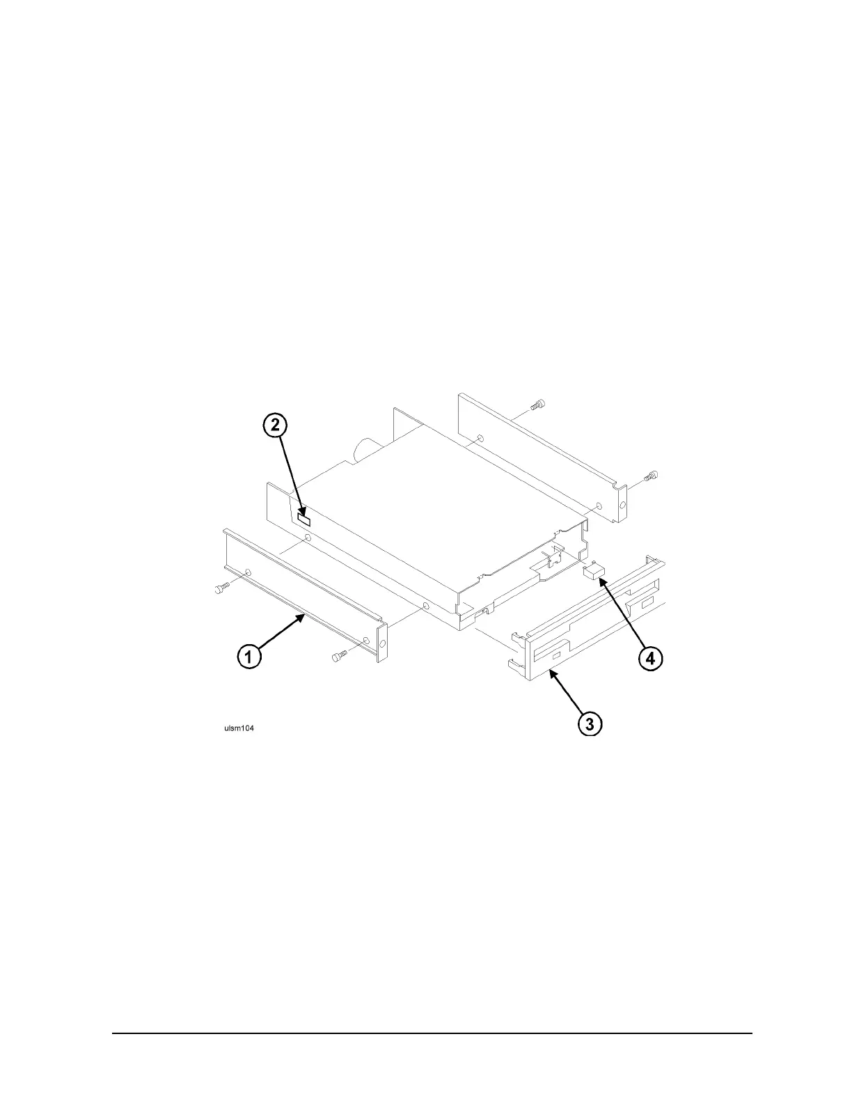
Assembling the IDE Floppy Disk
This procedure describes how to assemble the IDE Floppy device in the device tray itself. Refer to
Figure 10-18.
1. Remove the rails (1) from the old IDE device by removing the four mounting screws (two on each
side).
2. Remove the top of the device tray by gently prying the side of the top at the detent (2), lifting the
top off.
3. Remove the front bezel (3) by gently prying the bezel retaining pins and pulling it away.
4. Remove the eject button (4) by lifting it off the device metal button shoulders.
5. Remove the failed IDE Floppy device from the tray.
Figure 10-18IDE Floppy Disk Assembly Diagram
6. Install the new (0950-3092) IDE Floppy disk into the mounting tray.
7. Install the eject button. With the buttons tabs up, align the grooves in the button with the shoulders
on the disks metal tab and slide the button down.
8. Install the bezel. Align the bezels side clips with the frame of the tray and push until the clips lock.
9. Attach the rails to the assemble, refer to Figure 10-18.
10.Refer to Replace the IDE Floppy for mounting into the system chassis.
 Loading...