C-10 Appendix C
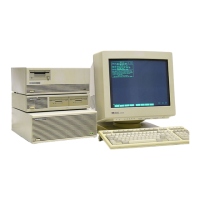
HotSwap Disk Bay (D Class Only)
Module Replacement Process
HotSwap Strategy:
The ability to connect or disconnect a SCSI device from an active bus depends primarily
on a strategy of non-intrusive electrical connectivity. The device being changed must
neither affect the SCSI bus logic state nor change power supply levels.
Hot plugging is limited to devices that have relinquished the bus and are not active for
the duration of the interchange. When this requirement is satisfied, the affected device
will tri-state all SCSI lines becoming completely transparent to all bus activity.
Furthermore, newly inserted devices will exhibit a similar high impedance state for a
period of time adequate for normal module insertion. As a result of this tri-state feature,
a device can be freely connected or disconnected from the active bus without loss of bus
integrity. Low bus impedances eliminate concerns over capacitive loading of bus lines by
newly inserted devices.
Power supply anomalies are primarily a concern upon insertion of a new device to the
system and not when removed. Upon insertion, the bulk storage capacitance resident on
a device's +5V and +12V supply lines must be charged. If connected instantaneously,
charged currents to fully discharged capacitors will become very high and tend to reduce
supply voltages. To prevent this problem, two slow-charge circuits are provided on the
interface PCA in the module assembly. These active circuits use a simple resistor
capacitor delay in combination with power FETs to limit charge currents to a
manageable level. These slow-charge circuits are used in combination with several large
bulk storage capacitors on the backplane PCA to reduce power surge effects to
insignificant levels.
Pin sequencing is used to detect when a module is either moving into the HotSwap
assembly or out of it. This is used to provide SCSI reset protection from data integrity
problems possible during hot-plug events.
Electrostatic discharge (ESD) caused failures were also considered in this design. The
potential for large charge differences between the modules and the HotSwap assembly,
prior to insertion, is large. The HotSwap design uses the module alignment pins to
provide electrical commonality between the system chassis and the module shield prior
to SCSI bus or power supply connection.
NOTE The ability to remove and replace hot-plugable modules on an active system
requires a large amount of software support. At the time of this document,
this support is not fully functional. Therefore special procedures for
managing the system and working with LVM have been generated. These
procedures will be available with the system documentation when the HP
9000 D Class Servers are released. In all cases, the SCSI bus activity
should be minimized before a disk module is removed or replaced with the
system active. (Refer to Manual HotSwap Procedure)
 Loading...