Chapter 11 11-35
SCSI Peripherals and I/O Information
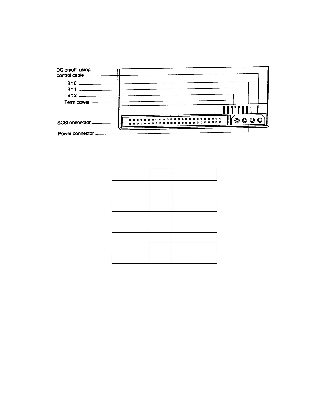
Figure 11-12 shows the rear view of the A3183A
Figure 11-12 A3183A Jumper Diagram
There are three significant bits in the ID, giving an ID range of 0 to 7 inclusive as shown:
Table 11-17 SCSI ID
1 = shorted, 0 = open
The HP A3183A reads the SCSI ID at power up and during selftest in order to determine the selected
target ID of the tape drive on the interface bus. Data Compression Control is not used in this system
application. Terminator Power - When jumper is installed, the device will supply termination power to
pin 26 of the SCSI bus. (Note, this device has no on board termination capability.)
Default Jumper Settings = Term Power Disabled (no jumper)
Configuration Switches
Figure 11-13 shows the configuration switches located on the bottom of the A3183A in their default
positions.
SCSI ID Bit 2 Bit 1 Bit 0
0 000
1 001
2 010
3 011
4 100
5 101
6 110
7 111
 Loading...