TRANSMISSION
B2650HSDC, B3350HSDC, WSM
2-M28
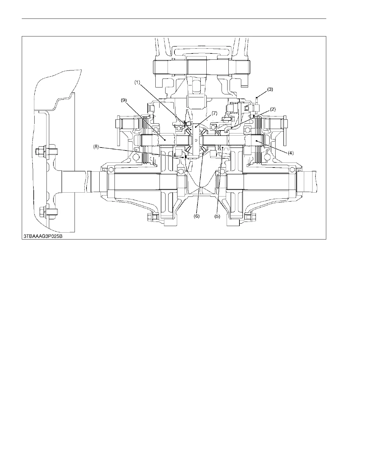
[2] DIFFERENTIAL LOCK
When resistance to the right and the left tires are greatly different due to ground conditions or type of work, the
tire with less resistance slips and prevents the tractor from moving ahead. To compensate for this drawback, the
differential lock restricts the differential action and causes both rear axles to rotate as a unit.
When the differential lock pedal is stepped on, it causes the differential lock lever (3) to rotate. The differential
lock lever (3) will move the shift fork (2) and the differential lock clutch (5) toward the spiral bevel pinion (8). The
differential lock clutch (5) engages with the teeth of the differential case (6) to make the differential case (6) and the
differential lock clutch (5) to rotate together as a unit.
Therefore, the differential pinions (1) are unable to rotate around the differential pinion shaft (7) and differential
revolutions are transmitted to the right and the left differential gear shaft (4), (9).
9Y1210822TRM0025US0
(1) Differential Pinion
(2) Shift Fork
(3) Differential Lock Lever
(4) Differential Gear Shaft (Right)
(5) Differential Lock Clutch
(6) Differential Case
(7) Differential Pinion Shaft
(8) Spiral Bevel Pinion
(9) Differential Gear Shaft (Left)
 Loading...