ELECTRICAL SYSTEM
B2650HSDC, B3350HSDC, WSM
8-S34
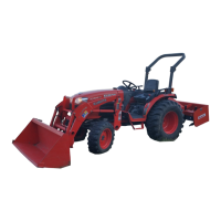
(10) Air Valve
• Check the actuation of air valve 1 and 2 before following checking.
1. Remove the double flare pipes from air valve 1 and 2 outlet.
2. Do active test "All Devices for Fuel Reformer Operate Function" by using diagmaster, then check if
the air comes out from air valve outlet (Refer to "Diagnosis Manual V1505-T-E4 (9Y120-02490)").
• It is possible to check the continuity of Yellow / Green wire by using active test "Air Valve 1 for Fuel
Reformer Operate Function".
• It is possible to check the continuity of White / Green wire by using active test "Air Valve 2 for Fuel
Reformer Operate Function".
9Y1210822ELS0118US0
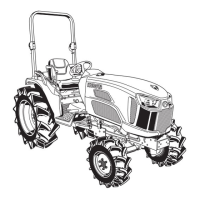
Connector Voltage
1. Disconnect the connector, and turn the main key switch "ON"
position.
2. Measure the voltage with a voltmeter across the terminals
shown in the table below.
3. If the reference value is not indicated as shown in the table
below, check the relating electric circuit.
9Y1210822ELS0119US0
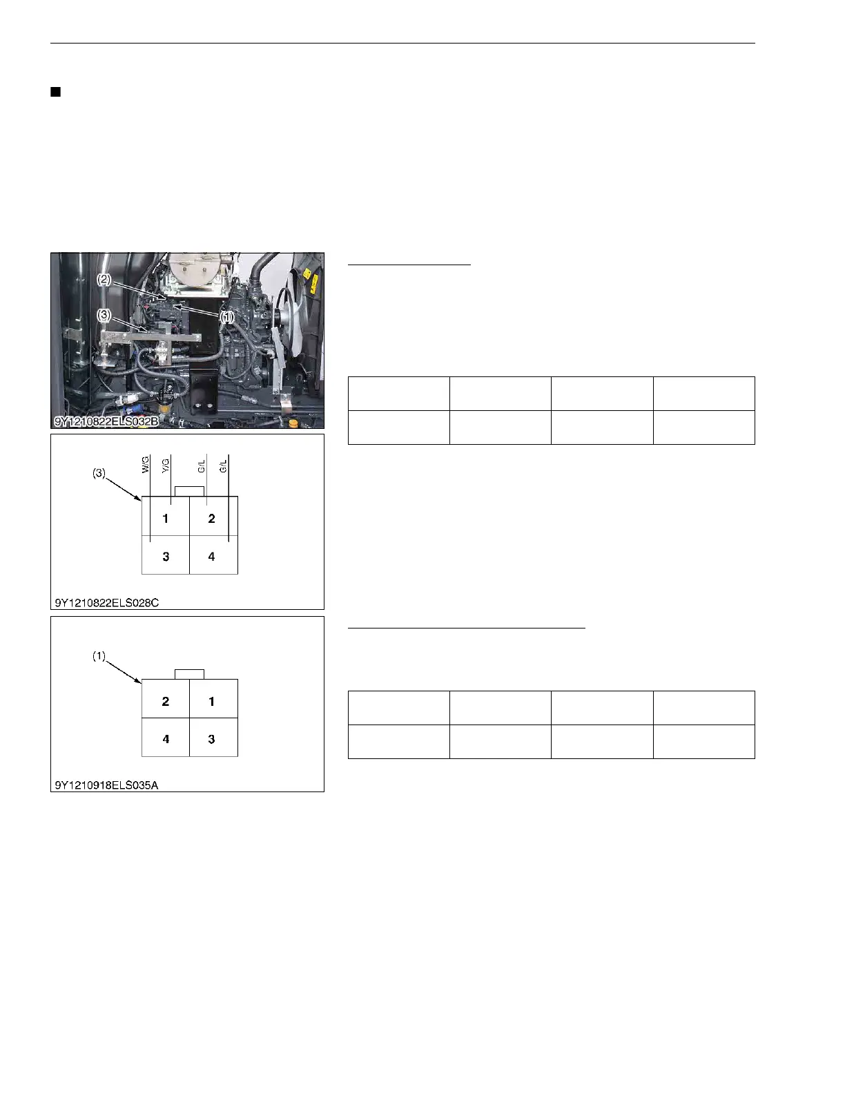
Solenoid Resistance (for Reference)
1. Measure the resistance with an ohmmeter across the terminals
shown in the table below.
2. If the reference value is not indicated, the air valve is faulty.
9Y1210822ELS0120US0
Air valve 1
Main switch at
"ON"
Terminal 2 –
chassis
Approx. battery
voltage
Air valve 2
Main switch at
"ON"
Terminal 4 –
chassis
Approx. battery
voltage
(1) Air Valve 1
(2) Air Valve 2
(3) Connector (Harness Side)
Resistance
(Air valve 1)
at 20 °C (68 °F) Terminal 1 – 2 Approx. 12 Ω
Resistance
(Air valve 2)
at 20 °C (68 °F) Terminal 3 – 4 Approx. 12 Ω
(1) Connector (Air Valve Side)
 Loading...