ELECTRICAL SYSTEM
B2650HSDC, B3350HSDC, WSM
8-S23
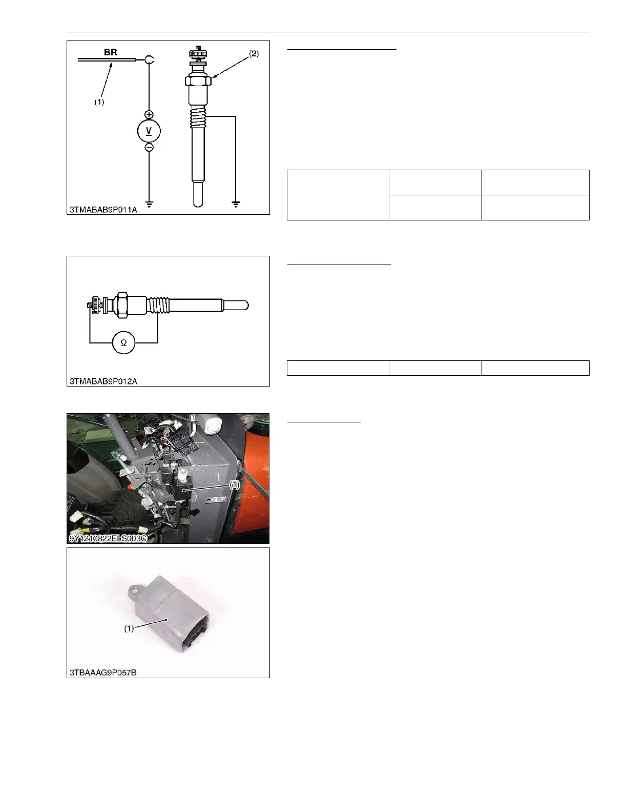
Lead Terminal Voltage
1. Disconnect the wiring lead (1) from the glow plug (2) after
turning the main switch off.
2. Turn the main switch key to the "PREHEAT" position, and
measure the voltage between the lead terminal and the chassis.
3. Turn the main switch key to the "START" position, and
measure the voltage with a voltmeter between the lead terminal
and the chassis.
4. If the voltage at either position differs from the battery voltage,
the wiring harness or main switch is faulty.
9Y1210822ELS0016US0
Glow Plug Continuity
1. Disconnect the leads from the glow plugs.
2. Measure the resistance with an ohmmeter between the glow
plug terminal and chassis.
3. If 0 Ω is indicated, the screw at the tip of the glow plug and the
housing are short-circuited.
4. If the factory specification is not indicated, the glow plug is
faulty.
9Y1210822ELS0017US0
(5) OPC Controller (B2650)
OPC Controller
1. Check the "Engine Starting Conditions" and "Automatic Engine
Stop Conditions" (See page 8-M10).
2. If the tractor does not operate appropriately, check all parts
according to the "1. TROUBLESHOOTING" section.
3. If all parts except the OPC controller (1) is not damaged, replace
the OPC controller (1).
9Y1210822ELS0028US0
Voltage (Lead terminal –
Chassis)
Main switch key at
"PREHEAT"
Approx. battery voltage
Main switch key at
"START"
Approx. battery voltage
(1) Wiring Lead (2) Glow Plug
Glow plug resistance Factory specification Approx. 1.1 Ω
(1) OPC Controller
 Loading...