ELECTRICAL SYSTEM
B2650HSDC, B3350HSDC, WSM
8-M5
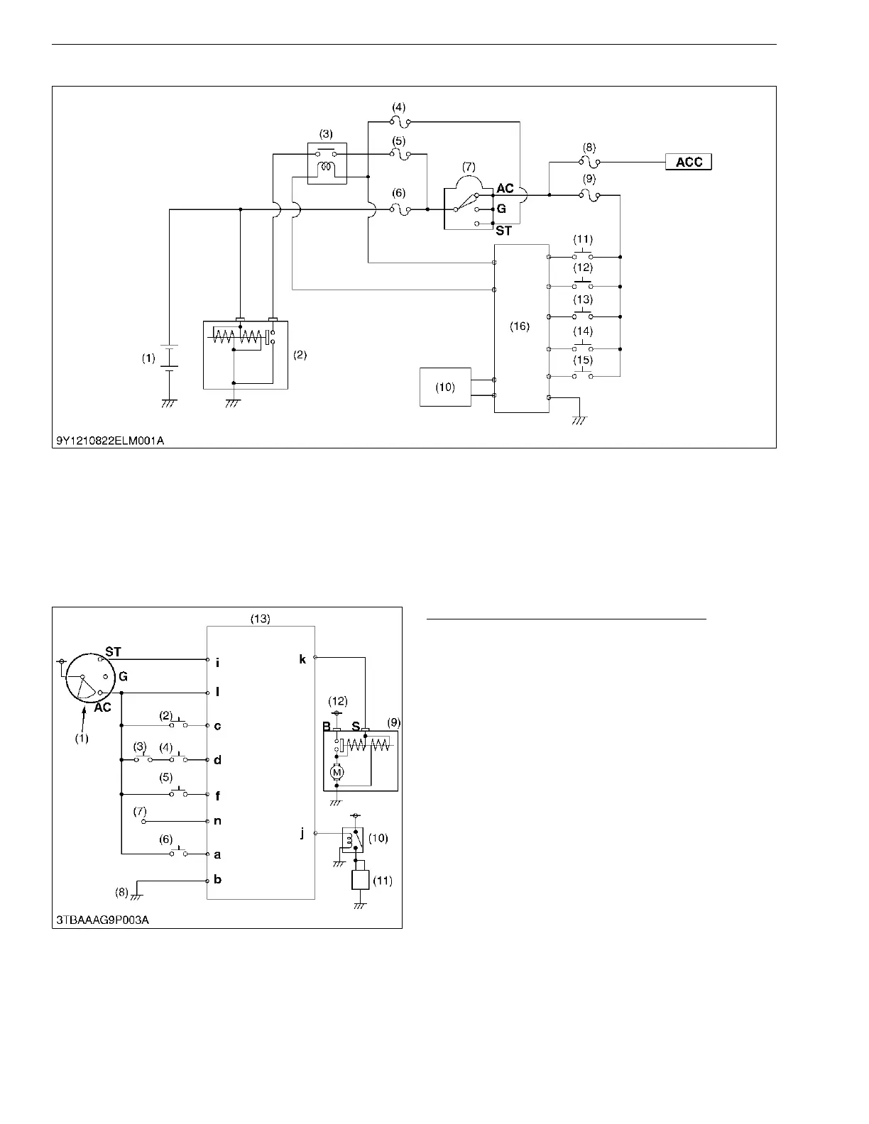
[2] OPC SYSTEM CIRCUIT (B3350)
9Y1210822ELM0003US0
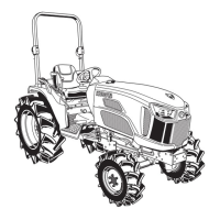
[3] CONTROLLER (B2650)
Operator Presence Control (OPC) System
B2650 is configured with an "Operator Presence
Control (OPC)" system to control engine starting and
engine automatically stopping.
This OPC system mainly consists of controller and
engine starting / stopping control switches such as HST
pedal switch, independent PTO lever switch, seat
switch, parking brake switch and PTO lever switch.
Main parts regarding OPC system are laid out as
shown in the electrical circuit.
9Y1210822ELM0004US0
(1) Battery
(2) Starter Motor
(3) Relay Stator
(4) Fuse (5 A)
(5) Fuse (30 A)
(6) Slow Blow Fuse (60 A)
(7) Main Switch
(8) Fuse (5 A)
(9) Fuse (5 A)
(10) Governor Solenoid
(11) Parking Brake Switch
(12) Seat Switch
(13) Independent PTO Lever
Switch
(14) HST Pedal Switch
(15) PTO Shift Lever Switch
(16) ECU
AC :AC Terminal
G : G Terminal
ST : ST Terminal
(1) Main Switch
(2) Independent PTO Lever
Switch
(3) Parking Brake Switch
(4) PTO Lever Switch
(5) Seat Switch
(6) HST Pedal Switch
(7) Regulator L Terminal
(8) Body Earth
(9) Starter Motor
(10) Key Stop Solenoid Relay
(11) Key Stop Solenoid
(12) Battery
(13) OPC Controller
a to l :Controller Terminal
ST : Main Switch ST Terminal
G : Main Switch G Terminal
AC :Main Switch AC Terminal
B : Starter Motor B Terminal
S : Starter Motor S Terminal