HYDRAULIC SYSTEM
B2650HSDC, B3350HSDC, WSM
7-M14
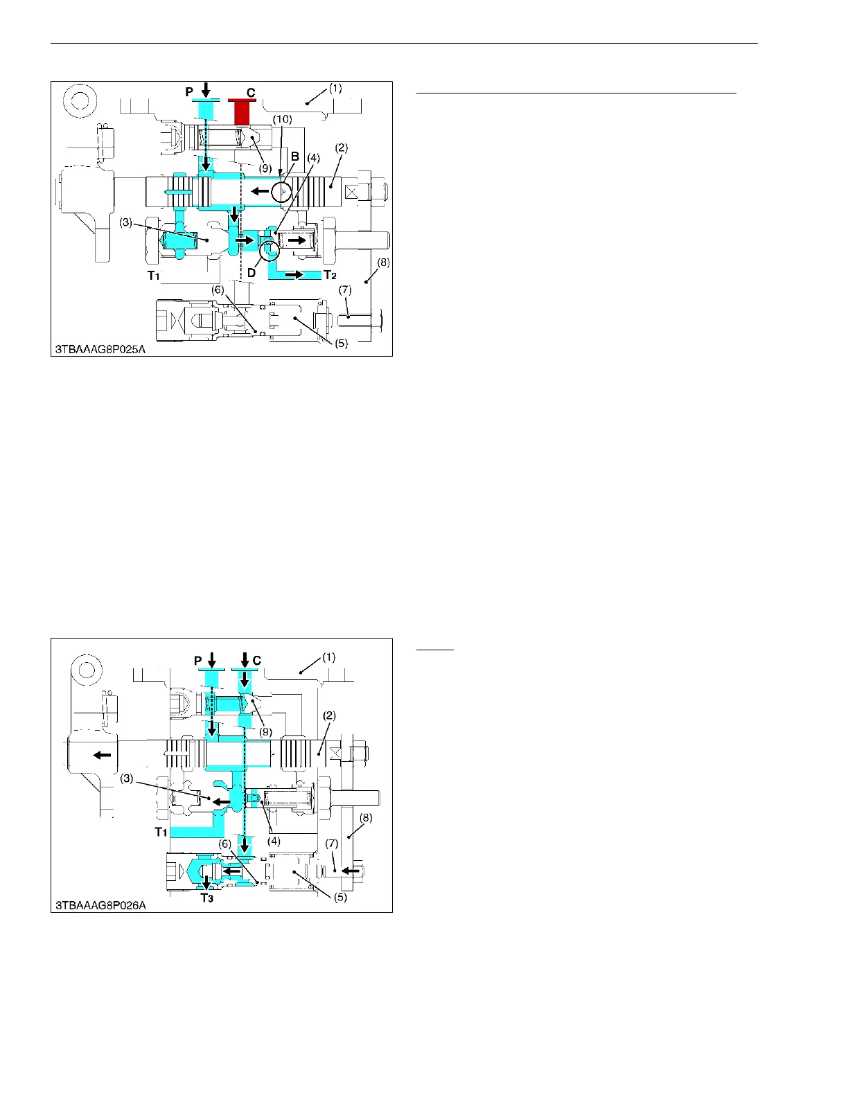
(3) Shockless Mechanism Operating (Lift to Neutral)
Shockless Mechanism Operating (Lift to Neutral)
When the implement begins to lift up, the feedback
rod connected to the lift arm pushes back the spool (2)
to near "NEUTRAL" position.
When the implement lifts up near the "NEUTRAL"
position, quantity of oil passing through the orifice (10) is
reduced.
It causes oil pressure difference between portion B
and unload poppet (4).
Since oil pressure at unload poppet (4) is higher than
oil pressure at portion D, oil forced from P port pushes
and opens unload poppet (4), and oil drains through T2
port to transmission case.
Quantity of oil flowing through portion B is less.
Quantity of oil flowing to unload poppet (4) is greater.
It causes oil pressure increase at portion D of the
unload poppet (4).
While the implement is coming to "NEUTRAL"
position, quantity of oil flowing to spool (2) is reduced at
portion B. And then, oil drains through unload poppet (4)
to transmission case.
It causes implement's smooth stopping at
"NEUTRAL" position without shock.
9Y1210822HYM0017US0
(4) Down
Down
When the position control lever is set to "DOWN"
position, the spool (2) is pulled out from the control valve
body (1).
At the same time, the adjust bolt (7) connected to the
connecting plate (8) pushes the poppet (5) into the
control valve body (1). And then the poppet (5) is
opened.
Oil in the hydraulic cylinder is forced out through T3
port and T4 port to transmission case by the weight of
the implement, causing the implement to lower.
Oil forced into the control valve through P port
pushes and opens the unload valve (3) and returns to the
transmission case through T1 port.
9Y1210822HYM0018US0
(1) Valve Body
(2) Spool
(3) Unload Valve
(4) Unload Poppet
(5) Poppet 2
(6) Sleeve
(7) Adjusting Bolt
(8) Connecting Plate
(9) Check Valve
(10) Orifice
P : Pump Port
B : Portion B
C : Cylinder Port
D : Portion D
T1 : Tank Port
(1) Valve Body
(2) Spool
(3) Unload Valve
(4) Unload Poppet
(5) Poppet 2
(6) Sleeve
(7) Adjusting Bolt
(8) Connecting Plate
(9) Check Valve
P : Pump Port
C : Cylinder Port
T1 : Tank Port
T3 : Tank Port
T4 : Tank Port
 Loading...