ELECTRICAL SYSTEM
B2650HSDC, B3350HSDC, WSM
8-S43
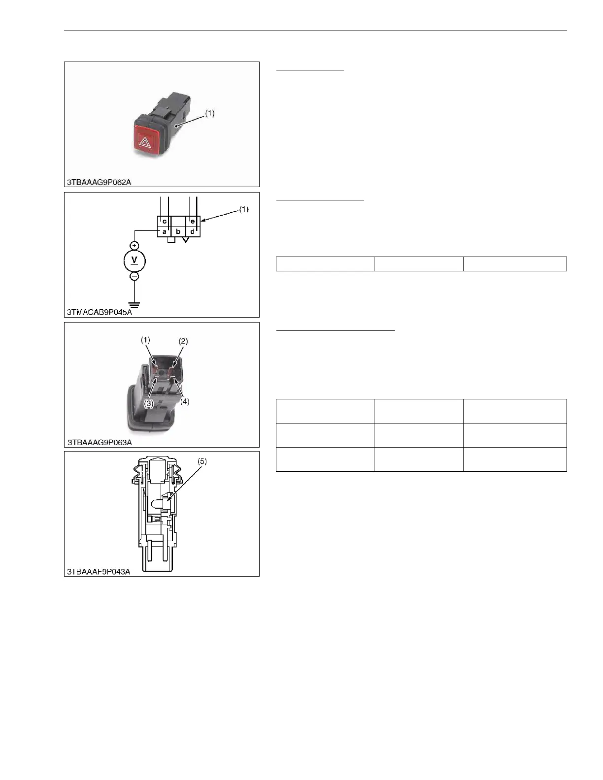
(2) Hazard Switch
Hazard Switch
1. Remove the meter panel and disconnect the 4P connector from
hazard switch after disconnecting the battery negative code.
2. Remove the hazard switch.
3. Perform the following check.
9Y1210822ELS0041US0
Connector Voltage
1. Connect the battery negative code, then measure the voltage
with a voltmeter across the a terminal and chassis.
2. If the voltage differ from the battery voltage, the wiring harness
is faulty.
9Y1210822ELS0042US0
Hazard Switch Continuity
1. Measure the resistance with ohmmeter across the a terminal (1)
and c terminal (3), and across the d terminal (2) and e terminal
(4).
2. If the measurement is not following below, the hazard switch or
the bulb are faulty.
9Y1210822ELS0043US0
(1) Hazard Switch
Voltage a terminal – Chassis Approx. battery voltage
(1) 4P Connector (for Hazard Switch)
Resistance
(Switch at OFF)
a terminal – c terminal Infinity
Resistance
(Switch at ON)
a terminal – c terminal 0 Ω
Resistance
(Bulb)
d terminal – e terminal Approx. 13 Ω
(1) a Terminal
(2) d Terminal
(3) c Terminal
(4) e Terminal
(5) Bulb
 Loading...