ELECTRICAL SYSTEM
B2650HSDC, B3350HSDC, WSM
8-S35
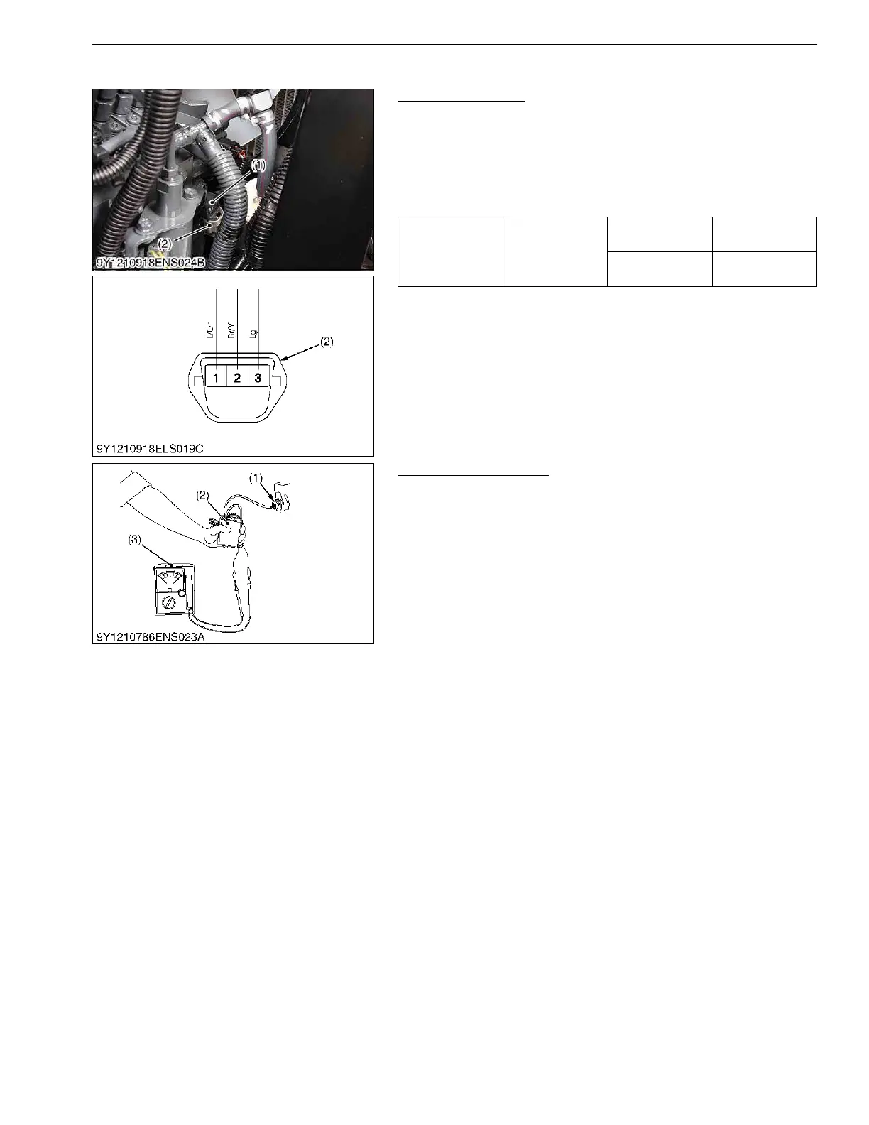
(11) Engine Speed Sensor (B3350)
Connector Voltage
1. Disconnect the connector, and turn the main key switch "ON"
position.
2. Measure the voltage with a voltmeter across the terminals
shown in the table below.
3. If the reference value is not indicated as shown in the table
below, check the relating electric circuit.
9Y1210822ELS0121US0
Sensor Actuation Test
1. Disconnect the connector of the engine speed sensor.
2. Connect a connector of the rotation sensor signal interface unit
(2) (see page G-48) to the engine speed sensor (1).
3. Connect each clip of the rotation sensor signal interface unit (2)
to the same test lead color of the circuit tester (3).
4. Switch on the rotation sensor signal interface unit (2).
5. Turn the flywheel and make sure that the voltage of the engine
speed sensor goes from 0 → 5 V or 5 → 0 V.
6. If there is no change in the voltage, replace the engine speed
sensor.
9Y1210822ELS0122US0
Voltage
Main switch at
"ON"
Terminal 3 –
chassis
Approx. 10.6 V
Terminal 1 –
chassis
Approx. 4.3 V
(1) Engine Speed Sensor (2) Connector (Harness Side)
(1) Engine Speed Sensor
(2) Rotation Sensor Signal Interface
Unit
(3) Circuit Tester
 Loading...