ELECTRICAL SYSTEM
B2650HSDC, B3350HSDC, WSM
8-S47
[8] WARNING LAMP, INDICATOR LAMP AND GAUGE
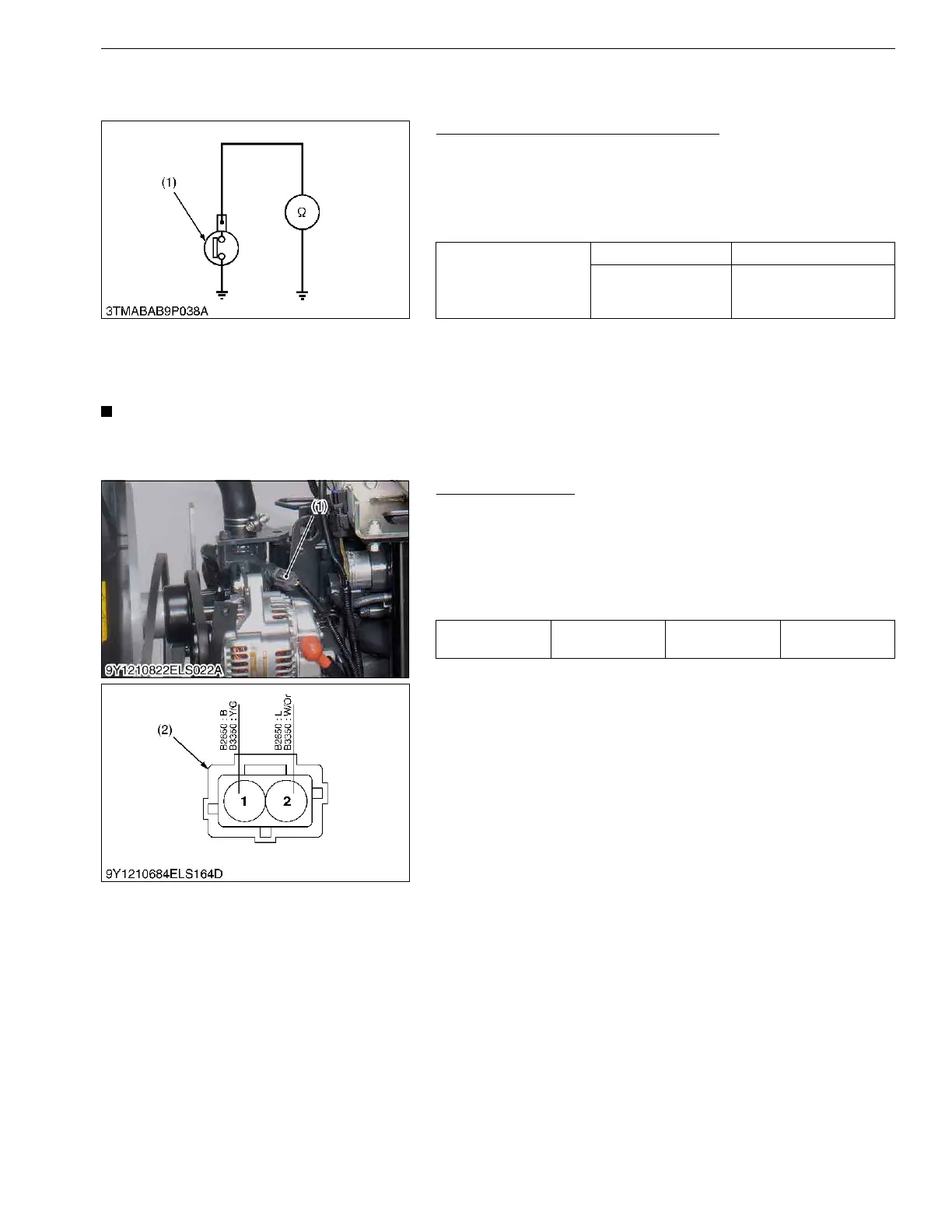
(1) Engine Oil Pressure Switch
Engine Oil Pressure Switch Continuity
1. Measure the resistance with an ohmmeter across the switch
terminal and the chassis.
2. If 0 Ω is not indicated in the normal state, the switch is faulty.
3. If infinity is not indicated at pressure over 49 kPa (0.50 kgf/cm
2
,
7.1 psi), the switch is faulty.
9Y1210822ELS0056US0
(2) Coolant Temperature Sensor
• Firstly check the connector voltage, secondly check the other wires continuity, then finally check the
sensor resistance.
9Y1210822ELS0058US0
Connector Voltage
1. Disconnect the connector and turn the main key switch "ON"
position.
2. Measure the voltage with a voltmeter across the terminals
shown in the table below.
3. If the reference value is not indicated as shown in the table
below, check the relating electric circuit.
9Y1210822ELS0059US0
Resistance (Switch
terminal – Chassis)
In normal state 0 Ω
At pressure over
approx. 49 kPa (0.50
kgf/cm
2
, 7.1 psi)
Infinity
(1) Engine Oil Pressure Switch
Voltage
Main switch at
"ON"
Terminal 2 –
chassis
Approx. 5 V
(1) Coolant Temperature Sensor (2) Connector (Harness Side)