HYDRAULIC SYSTEM
B2650HSDC, B3350HSDC, WSM
7-M15
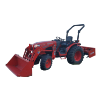
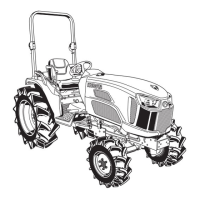
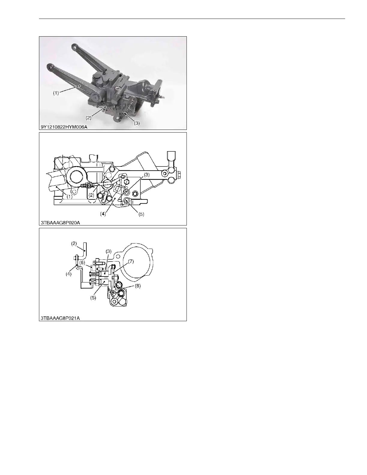
[5] FEEDBACK LINKAGE FOR POSITION CONTROL
When the position control lever is moved to rearward
to lift the implement, the spool of the position control
valve is pushed in to form a lifting circuit by the motions
of the control lever arm, the control lever shaft (3), the
connecting arm (7) and the lever (8). After the lift arm (1)
moves upward, the spool is pulled out and returns to
form a neutral circuit by the motions of the feedback rod
(2), the feedback arm (4), the feedback, the arm shaft
(5), the connecting arm (7) and the lever (8).
As a result, the implement height can be easily
determined in proportion to the set position of the
position control lever.
9Y1210822HYM0019US0
(1) Lift Arm
(2) Feedback Rod
(3) Control Lever Shaft
(4) Feedback Arm
(5) Feedback Arm Shaft
(6) Control Lever Arm
(7) Connecting Arm
(8) Lever
 Loading...