HYDRAULIC SYSTEM
B2650HSDC, B3350HSDC, WSM
7-S15
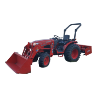
(3) Hydraulic Control Valve
Disassembling Position Control Valve
1. After removing the control valve, disassemble the component
parts as shown in the picture.
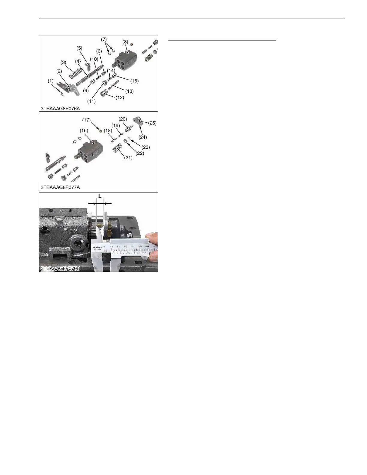
(When reassembling)
• Readjust the length "L" of the adjusting bolt.
(Reference)
• Length "L": approximately 10.70 mm (0.4213 in.)
9Y1210822HYS0033US0
(1) External Circlip
(2) Lever
(3) Spring
(4) Spool
(5) Spring Holder
(6) Poppet
(7) O-ring
(8) Control Valve Body
(9) Plug
(10) Spring
(11) Unload Plug
(12) Plug
(13) Poppet
(14) Spring
(15) Unload Poppet
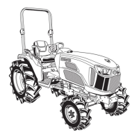
(16) Control Valve Body
(17) Nut
(18) Poppet
(19) Spring
(20) Plug
(21) Spring
(22) Spring Holder
(23) External Circlip
(24) Adjusting Bolt
(25) Connecting Plate
L: Length of adjusting bolt
 Loading...