ELECTRICAL SYSTEM
B2650HSDC, B3350HSDC, WSM
8-S13
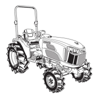
Connector Voltage
(Main Circuit)
1. Turn on the main switch. (Do not start engine.)
2. Measure the voltage between terminal 1 or 2 (+) and terminal 19
(−).
3. It is OK if the voltage equals to the battery voltage.
(Voltage)
1. Turn on the main switch. (Do not start engine.)
2. Measure the voltage between terminal 11 or 29 or 30 (+) and
terminal 19 (−).
3. It is OK if the voltage is approx. 5 V.
9Y1210822ELS0054US0
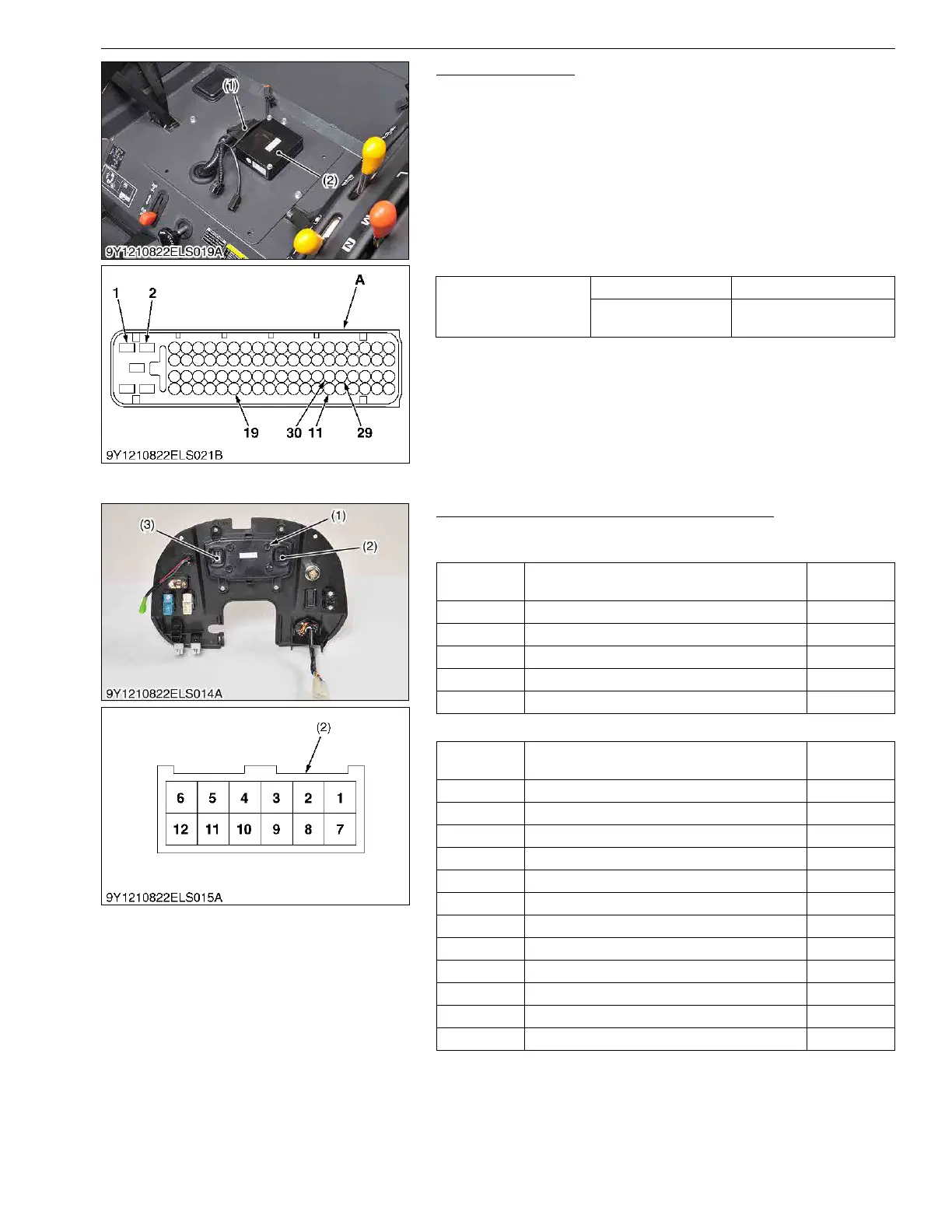
(2) Meter Panel
Arrangement of Digital Display Connector Pin
B2650
[Connector 1]
[Connector 2]
(To be continued)
Voltage
Terminal 1 or 2 to 19 Approx. battery voltage
Terminal 11 or 29 or 30
to 19
Approx. 5 V
(1) ECU Connector
(2) ECU
A : ECU Connector of Wire Harness
Side
Terminal
No.
Item
Color of
wiring
1 to 5 Blank –
6L Terminal L/R
7 to 10 Blank –
11 PTO ON/OFF Lg
12 Turn Signal (L) Sb
Terminal
No.
Item
Color of
wiring
1 Turn Signal (R) V
2 Glow Plug W
3 Oil Switch W/R
4 to 8 Blank –
9 Fuel Gauge V
10 Water Temperature Gauge L
11 GND B
12 Panel Meter Switch P/W
13 Engine Revolution Sb
14 Blank –
15 Battery Y/L
16 Main Switch Br
(1) Digital Display
(2) Connector 1 (Display Side)
(3) Connector 2 (Display Side)
 Loading...