HYDRAULIC SYSTEM
B2650HSDC, B3350HSDC, WSM
7-M3
3. THREE POINTS HYDRAULIC SYSTEM
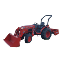
[1] HYDRAULIC CIRCUIT
Two hydraulic pumps (4) (6) are installed in the
B2650 and B3350.
Hydraulic oil is forced from hydraulic pump (6) to the
loader control valve (7), relief valve (8), hydraulic block
(9) and position control valve (10).
Three point hydraulic oil pressure is controlled by the
relief valve (8).
9Y1210822HYM0003US0
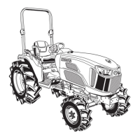
[2] FRONT LOADER CONTROL VALVE
(1) Structure
The control valve assembly consists of one casting
block and four major section as shown above.
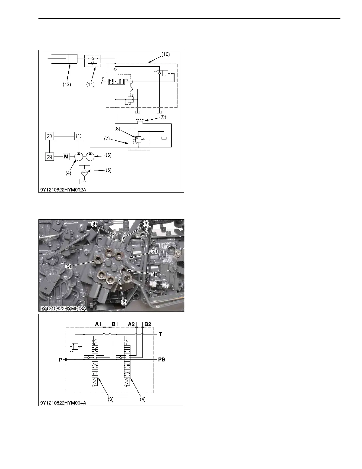
1) Inlet and Outlet Section
This section has P and T ports.
The P port is connected to the OUTLET port of
hydraulic block by the hydraulic hose.
The T port is connected to the TANK port of
hydraulic block by the hydraulic hose.
2) Boom Control Section
The boom control valve is consists of 4-position,
6-connection, detent, spring center type, consisting of a
mono block valve housing, spool, load check valve, etc.
This valve has A1 and B1 ports and controls oil flow to
the boom cylinder.
3) Bucket Control Section
The bucket control valve is consists of 4-position,
6-connection, no detent, spring center type, consisting of
a mono block valve housing, spool, load check valve,
etc. This valve has A2 and B2 ports and controls oil flow
to the bucket cylinder.
4) Power Beyond
This section has PB port which is connected to the
INLET port of hydraulic block by the hydraulic hose, and
feeds oil to the 3-point hitch hydraulic control valve.
9Y1210822HYM0004US0
(1) Power Steering Controller
(2) Independent PTO
(3) HST
(4) Hydraulic Pump (for Power
Steering, HST, and
Independent PTO)
(5) Oil Filter Cartridge
(6) Hydraulic Pump (for 3-Points
Hitch)
(7) Loader Control Valve
(8) Relief Valve
(9) Hydraulic Block (Hydraulic
Cylinder Block)
(10) Position Control Valve
(11) Lowering Speed Adjusting
Valve
(12) Hydraulic Cylinder
(1) Pump Port
(2) Tank Port
(3) Boom Control Spool
(4) Bucket Control Spool
(5) Power Beyond Port
(6) Loader Valve Assembly
P: P Port
T: T Port
A1: A1 Port
A2: A2 Port
B1: B1 Port
B2: B2 Port
PB: PB Port
 Loading...