HYDRAULIC SYSTEM
B2650HSDC, B3350HSDC, WSM
7-S17
[4] SERVICING
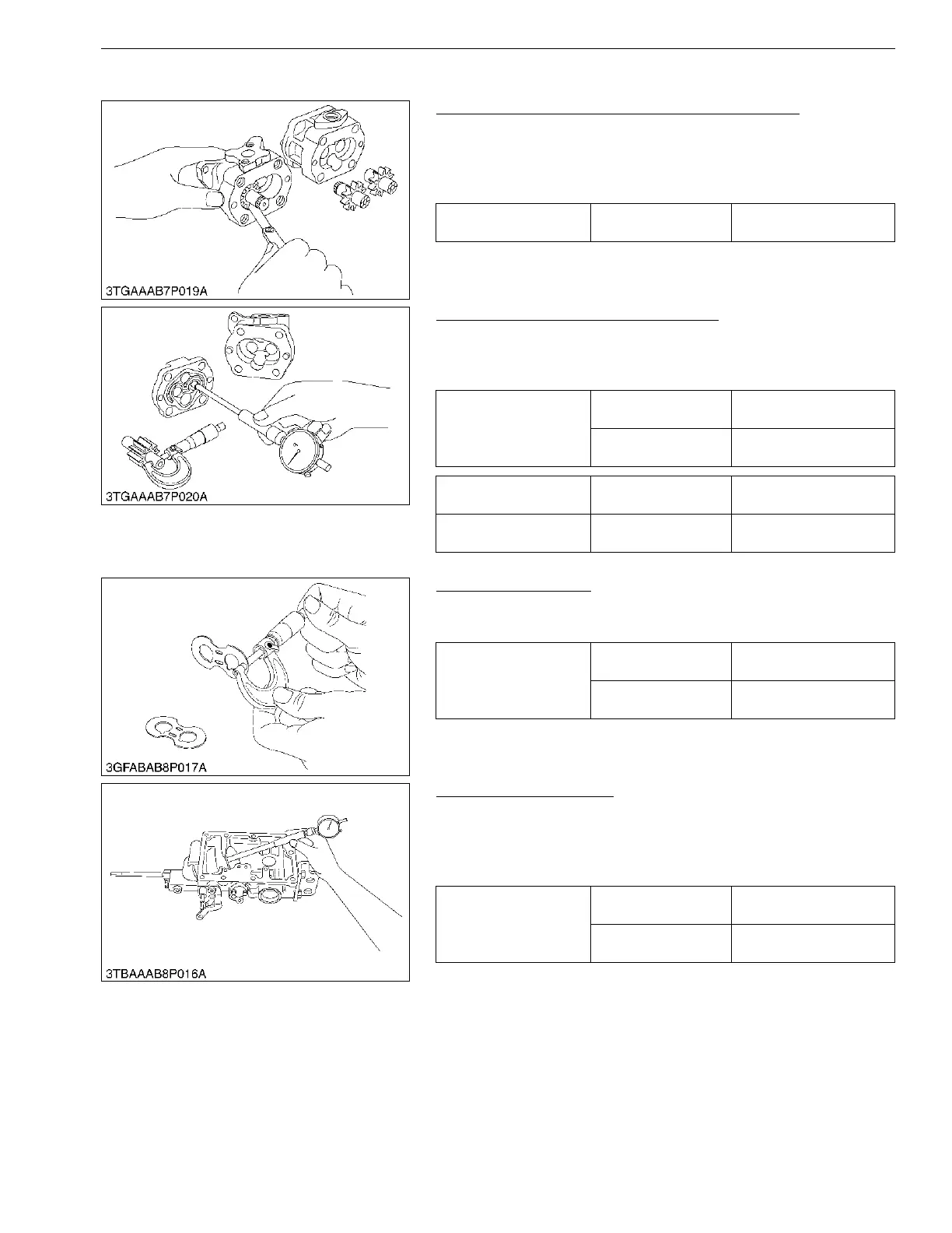
Clearance between Tip of Gear Tooth and Casing
1. Measure the clearance between gear and casing at several
points with feeler gauge.
2. If the clearance exceeds the allowable limit, replace the
assembly.
9Y1210822HYS0035US0
Clearance between Bushing and Shaft
1. Measure the shaft O.D. with an outside micrometer.
2. Measure the bushing I.D. with a cylinder gauge.
3. If the clearance exceeds the allowable limit, replace it.
9Y1210822HYS0036US0
Side Plate Thickness
1. Measure the side plate thickness with an outside micrometer.
2. If the thickness is less than the allowable limit, replace it.
9Y1210822HYS0037US0
Hydraulic Cylinder Bore
1. Check the cylinder internal surface for scoring or damage.
2. Measure the cylinder I.D. with a cylinder gauge.
3. If the measurement exceeds the allowable limit, replace the
hydraulic cylinder block.
9Y1210822HYS0038US0
Clearance between tip of
gear tooth and casing
Allowable limit
0.15 mm
0.0059 in.
Clearance between
bushing and shaft
Factory specification
0.020 to 0.091 mm
0.00079 to 0.0035 in.
Allowable limit
0.12 mm
0.0047 in.
Shaft O.D. Factory specification
14.970 to 14.980 mm
0.58937 to 0.58976 in.
Bushing I.D. Factory specification
15.000 to 15.061 mm
0.59056 to 0.59295 in.
Side plate thickness
Factory specification
2.48 to 2.50 mm
0.0977 to 0.0984 in.
Allowable limit
2.40 mm
0.0945 in.
Cylinder I.D.
Factory specification
75.05 to 75.10 mm
2.955 to 2.956 in.
Allowable limit
75.15 mm
2.959 in.
 Loading...