FRONT AXLE
B2650HSDC, B3350HSDC, WSM
5-S7
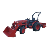
(2) Disassembling Front Assembly
Front Axle Brackets and Tie-rod Joints
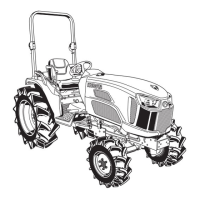
1. Remove the slotted nut (4) and remove the tie-rod end (3).
2. Remove the front axle brackets (1), (2).
(When reassembling)
• Apply grease to the thrust collar of front axle bracket.
• Apply grease to the O-ring and be careful not to damage it.
• After tightening the slotted nut, install cotter pin as shown in the
figure.
9Y1210822FAS0010US0
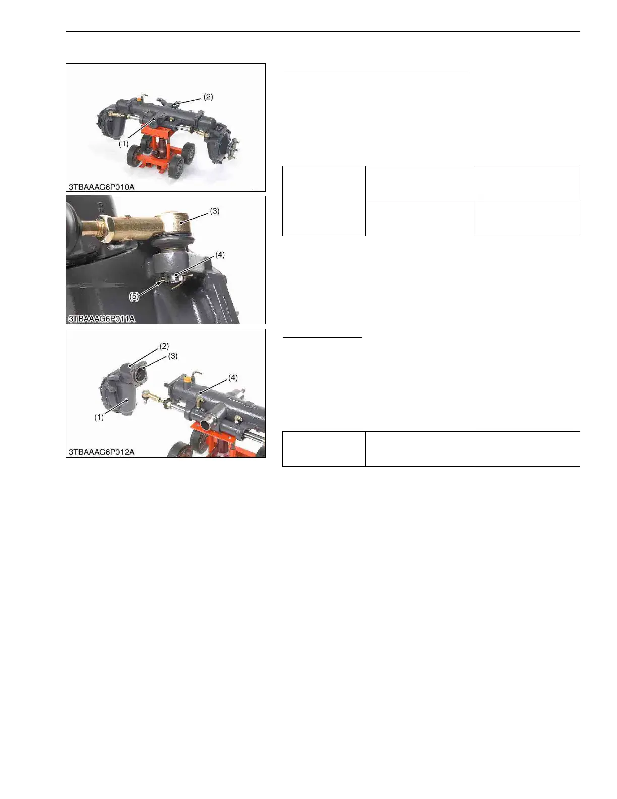
Bevel Gear Case
1. Remove the bevel gear case mounting screws.
2. Remove the bevel gear case (2) and front gear case (1) as a unit
from the front axle case (4).
(When reassembling)
• Apply grease to the O-ring (3) and be careful not to damage it.
• Do not interchange right and left bevel gear case assemblies
and right and left gear case assemblies.
9Y1210822FAS0011US0
Tightening torque
Tie-rod slotted nut
18 to 35 N·m
1.8 to 3.5 kgf·m
14 to 25 lbf·ft
Tie-rod joint
74 to 84 N·m
7.5 to 8.6 kgf·m
54.4 to 61.9 lbf·ft
(1) Front Axle Bracket (Front)
(2) Front Axle Bracket (Rear)
(3) Tie-rod End
(4) Slotted Nut
(5) Cotter Pin
Tightening torque
Bevel gear case mounting
screw
77.5 to 90.1 N·m
7.9 to 9.2 kgf·m
57.1 to 66.5 lbf·ft
(1) Front Gear Case
(2) Bevel Gear Case
(3) O-ring
(4) Front Axle Case
 Loading...