3.6.2 Structures of batch process cells
Process cell configuration with SIMATIC BATCH
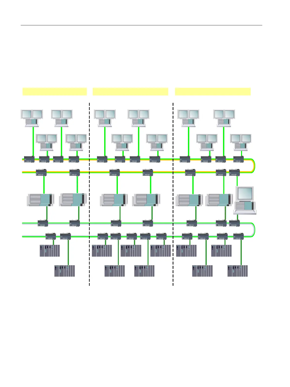
One possible structure of a complex SIMATIC BATCH process cell is shown in the following
figure.
%DWFKSURFHVVFHOO
&OLHQW26&OLHQW26
7HUPLQDOEXV
(6
$6
&OLHQW
%$7&+
&OLHQW
%$7&+
6HUYHU
UHGXQGDQW
%$7&+
$6
$6
$6
$6$6
$6
$6
$6
$6
$6
3ODQWEXV
%DWFKSURFHVVFHOO%DWFKSURFHVVFHOO
6HUYHU
UHGXQGDQW
26
6HUYHU
UHGXQGDQW
%$7&+
6HUYHU
UHGXQGDQW
26
6HUYHU
UHGXQGDQW
%$7&+
6HUYHU
UHGXQGDQW
26
&OLHQW26&OLHQW26&OLHQW26&OLHQW26
&OLHQW
%$7&+
&OLHQW
%$7&+
&OLHQW
%$7&+
&OLHQW
%$7&+
Image 3-3 Process cell configuration
Operating batch process cells
The "Process cell configuration" figure shows that three batch process cells can exist
completely independently of each other on one common terminal and plant bus. Normally,
however, one batch process cell is adequate. A distribution over several batch process cells
is necessary only with very complex process engineering plants with an extremely large
quantity structure.
Product introduction and installation
3.6 Configuration limits
SIMATIC BATCH V8.2
68 Operating Manual, 02/2016, A5E35958174-AA
 Loading...


