1
Introduction 10.04
1.4 Fundamentals
1
Siemens AG, 2004. All rights reserved
1-48 SINUMERIK 840D/840Di/810D Operation/Programming ShopMill (BAS) – 10.04 Edition
1.4 Fundamentals
1.4.1 Plane designation
A plane is defined by means of two coordinate axes. The third
coordinate axis (tool axis) is perpendicular to this plane and
determines the infeed direction of the tool (e.g. for 2½-D machining).
When programming, it is
necessary to specify the working
plane so that the control system
can calculate the tool offset values
correctly. The plane is also
relevant to certain types of circular
programming and polar
coordinates.
X
Y
Z
Y
/
Z
Z
/
X
X
/
Y
Working planes are defined as follows:
Plane Tool axis
X/Y Z
Z/X Y
Y/Z X
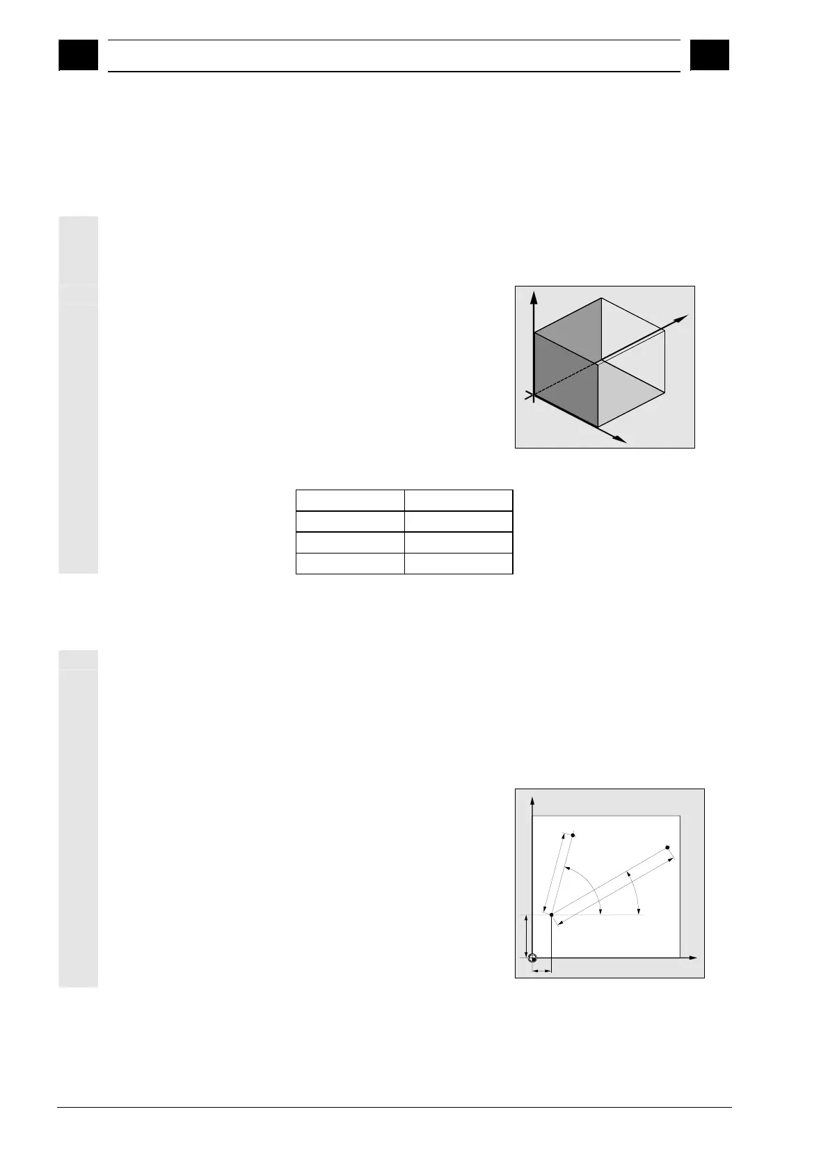
1.4.2 Polar coordinates
The rectangular coordinate system is suitable in cases where
dimensions in the production drawing are orthogonal. For workpieces
dimensioned with arcs or angles, it is better to define positions using
polar coordinates. This is possible if you are programming a straight
line or a circle (see Section "Programming simple path motions").
Polar coordinates have their zero point in the "pole".
Example:
Points P1 and P2 can then be
described – with reference to the
pole – as follows:
P1:radius =100 plus angle =30°
P2:radius =60 plus angle =75°
X
Y
P1
P2
30°
75°
Pole
15
30
6
0
1
0
0

 Loading...


