Detailed Description
2.4 Referencing with incremental measurement systems
Reference Point Approach (R1)
Function Manual, 08/2005 Edition, 6FC5397-0BP10-0BA0
2-7
2.4.2 Phase 1: Traversing to the reference cam
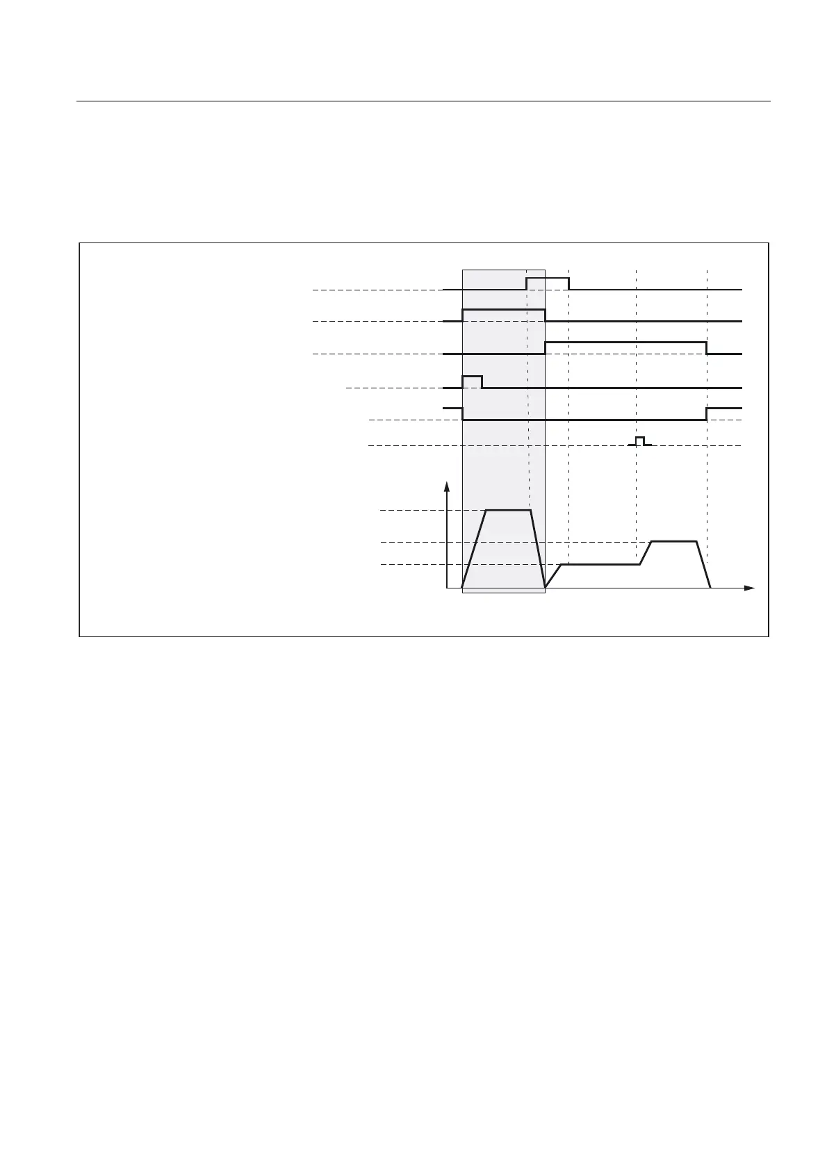
Phase 1: Graphic representation
'%'%;GHFHOHUDWLRQRIUHIHUHQFHSRLQWDSSURDFK
'%'%;PRWLRQFRPPDQGSOXV
'%'%;PRWLRQFRPPDQGPLQXV
'%'%;DQGWUDYHUVLQJNH\SOXVPLQXV
'%'%;DQGUHIHUHQFHGV\QFKURQL]HG
=HURPDUNSRVLWLRQPHDVXULQJV\VWHP
9HORFLW\
UHIHUHQFHSRLQWDSSURDFKYHORFLW\
UHIHUHQFHSRLQWFUHHSYHORFLW\
UHIHUHQFHSRLQWSRVLWLRQLQJYHORFLW\
3KDVH
0'0$B5()3B9(/2B6($5&+B&$0
0'0$B5()3B9(/2B6($5&+B0$5.(5
0'0$B5()3B9(/2B326
W
Fig. 2-2 Phase 1: Traversing to the reference cam
Phase 1: Start
For information on starting reference point approach, refer to "Axis-specific referencing" and
"Channel-specific referencing."
Phase 1: Sequence
In phase 1, depending on the position of the machine axis with reference to the homing cam,
we distinguish between three cases:
1. The machine axis is positioned before the reference cam
2. The machine axis is positioned on the reference cam
3. The machine axis has no reference cam
 Loading...


