Data Lists
5.2 Setting data
Spindles (S1)
Function Manual, 08/2005 Edition, 6FC5397-0BP10-0BA0
5-3
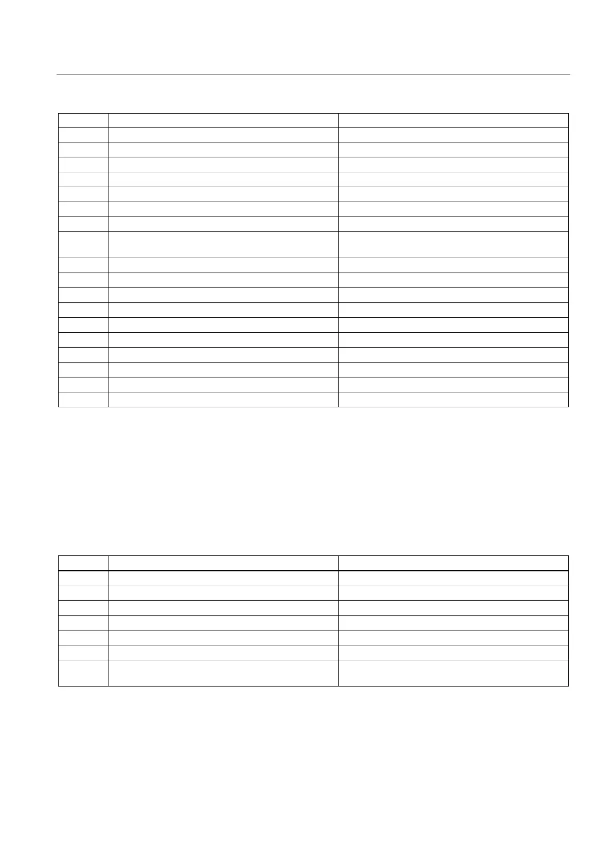
Number Identifier: $MA_ Description
35150 SPIND_DES_VELO_TOL Spindle speed tolerance
35160 SPIND_EXTERN_VELO_LIMIT Spindle speed limitation via PLC
35200 GEAR_STEP_SPEEDCTRL_ACCEL[n] Acceleration in speed control mode
35210 GEAR_STEP_POSCTRL_ACCEL[n] Acceleration in position control mode
35220 ACCEL_REDUCTION_SPEED_POINT Speed limit for reduced acceleration
35230 ACCEL_REDUCTION_FACTOR Reduced acceleration
35300 SPIND_POSCTRL_VELO position control activation speed
35350 SPIND_POSITIONING_DIR Positioning direction of rotation for a non-
synchronized spindle
35400 SPIND_OSCILL_DES_VELO Oscillation speed
35410 SPIND_OSCILL_ACCEL Oscillation acceleration
35430 SPIND_OSCILL_START_DIR Oscillation start direction
35440 SPIND_OSCILL_TIME_CW Oscillation time for M3 direction
35450 SPIND_OSCILL_TIME_CCW Oscillation time for M4 direction
35500 SPIND_ON_SPEED_AT_IPO_START Feed enable with spindle in setpoint range
35510 SPIND_STOPPED_AT_IPO_START Feed enable with stationary spindle
35590 PARAMSET_CHANGE_ENABLE Parameter set definition possible from PLC
36060 STANDSTILL_VELO_TOL Threshold velocity "Axis/spindle stationary"
36200 AX_VELO_LIMIT Threshold value for velocity monitoring.
5.2 5.2 Setting data
5.2.1 Channel-specific setting data
Number Identifier: $SC_ Description
42600 JOG_FEED_PER_REF_SOURCE Revolutional feedrate control in JOG mode
42800 SPIND_ASSIGN_TAB Spindle number converter
42900 MIRROR_TOOL_LENGTH Mirror tool length offset
42910 MIRROR_TOOL_WEAR Mirror wear values of tool length compensation
42920 WEAR_SIGN_CUTPOS Mirror wear values of machining plane
42930 WEAR_SIGN Invert sign of all wear values
42940 TOOL_LENGTH_CONST Retain the assignment of tool length components
when changing the machining plane (G17 to G19)
 Loading...


