Detailed description
2.4 Starting up the PLC program
Power Line Basic PLC Program (P3)
Function Manual, 08/2005 Edition, 6FC5397-0BP10-0BA0
2-21
2.4.7 Software upgrades
Software upgrade
Whenever you update the PLC or NCK software, always reset the PLC to its initial state first.
This initial clear state can be achieved by means of a general PLC reset. All existing blocks
are cleared when the PLC is reset.
It is usually necessary to include the new basic program when a new NC software version is
installed. The basic programs blocks must be loaded into the user project for this purpose.
OB 1, OB 40, OB 100, FC 12 and DB 4 should not be loaded if these blocks are already
included in the user project. These blocks may have been modified by the user. The new
basic program must be linked with the user program.
To do this, proceed as follows:
1. Generate the text or source file of all user blocks before copying the basic program.
2. Then copy the new basic program blocks to this machine project (for a description, see
Subsection "Application of basic program")
3. All user programs *.awl must then be recompiled in the correct order! (See also the
"Machine program" section.)
This newly compiled machine program must then be loaded to the PLC CPU using
STEP 7.
However, it is normally sufficient to recompile the organization blocks (OB) and the instance
data blocks of the machine program. This means you only need to generate sources for the
organization blocks and the instance data blocks (before upgrading).
Overall reset
A description of how to perform a general PLC reset appears in the Installation and Startup
Guide. However, a general reset does not delete the contents of the diagnostic buffer nor the
node address on the MPI bus. Another possible general reset method is described below.
This method must be used when the normal general reset process does not work.
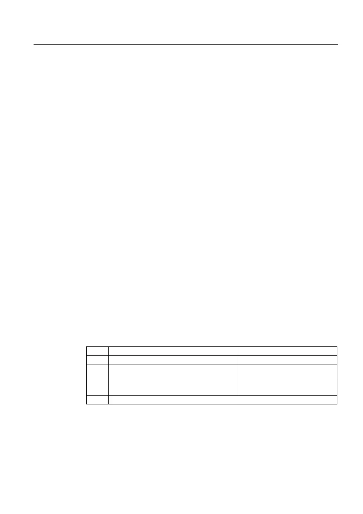
Proceed as follows:
No. Action Effect
1 Control system is switched off
2 PLC switch setting 3 (MRES) and switch control on
again or perform hardware reset.
LED labeled PS flashes slowly.
3 Set PLC startup switch to position 2 (STOP) and
back to position 3 (MRES).
The LED labeled PS starts to flash
faster.
4 Set PLC startup switch to setting 2 or 0.
 Loading...


