Detailed Description
2.2 Zeros and reference points
Axis Types, Coordinate Systems, Frames (K2)
2-20 Function Manual, 08/2005 Edition, 6FC5397-0BP10-0BA0
Note
The axis container functionality is currently not available with the SINUMERIK 840Di.
The axis container function is described in
References:
/FB2/ Description of Functions, Expansion Functions; Multiple Operator Panels on Multiple
NCUs, Distributed Systems (B3)
2.2 2.2 Zeros and reference points
2.2.1 Reference points in working space
The following zeros and reference points are defined in the working space, in which tools
move when machining workpieces:
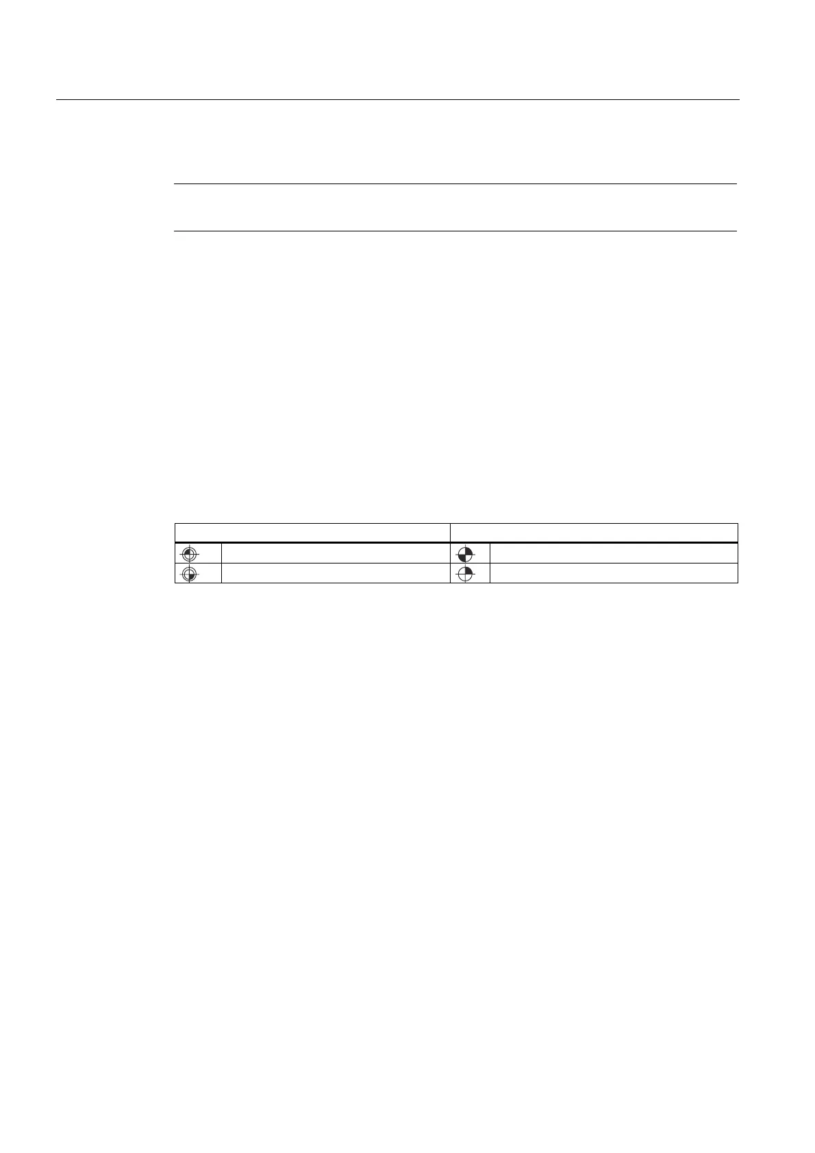
Table 2-1 Zeros and reference points
Zero points Reference points
M = Machine zero
R = Reference point
W = Workpiece zero
T = Toolholder reference point
• Machine zero M
The machine zero M defines the machine coordinate system MCS. All other reference
points refer to the machine zero.
• Workpiece zero W
The workpiece zero W defines the workpiece coordinate system in relation to the
machine zero M. The programmed part-program blocks are executed in the workpiece
coordinate system WCS.
• Reference point R
The position of the reference point R is defined by cam switches. Reference point R
calibrates the position measuring system.
With incremental encoders, the reference point must be approached every time the
control power is switched on. The control can only then work with the measuring system
and transfer all position values to the coordinate systems.
• Toolholder reference point T
The toolholder reference point T is located on the toolholder locator. By entering the tool
lengths, the control calculates the distance between the tool tip (TCP Tool Center Point)
and the toolholder reference point.

 Loading...


