Detailed Description
2.5 Optimization of the control
Velocities, Setpoint/Actual-Value Systems, Closed-Loop Control (G2)
Function Manual, 08/2005 Edition, 6FC5397-0BP10-0BA0
2-73
*UDSKLF7U$[LV;7U$[LV;!
*UDSKLF7U$[LV;7U$[LV;!
7U)ROORZLQJHUURU
7U$FWXDOSRVLWLRQPHDVXULQJV\VW
7U$FWXDOYHORFLW\
7U3RVLWLRQVHWSRLQW
0DUNHU;
0DUNHU;
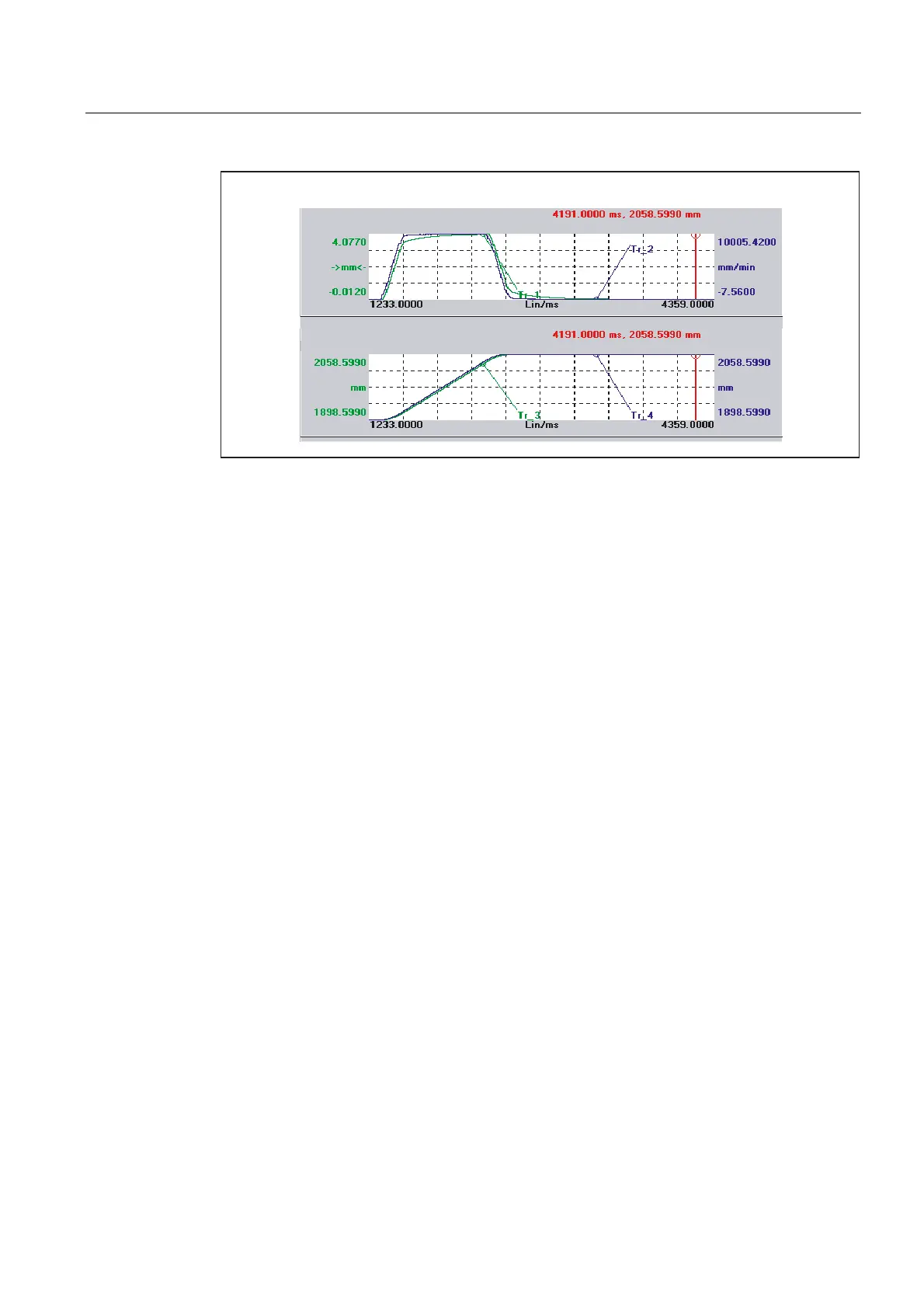
Fig. 2-14 Following error (1), actual velocity (2), position actual value (3), position setpoint (4)
2.5.5 System variable for status of pulse enable
Application
For all applications that must quickly react to pulse enabling, the status of the pulse enable is
imaged to a new system variable in order to accelerate the braking signal.
This system variable is preferably evaluated in synchronized actions. Using the synchronized
action, either a direct output to an NCK output can be carried out or a faster transfer to the
PLC.
Functionality
Since 611D digital drives have no integrated braking signal, the brakes are normally
controlled from the PLC. The brake can be closed again by deleting the pulse enable in the
PLC.
If the pulse enable is deleted due to external events (611D interface, terminal 663 to the
PLC) or due to drive or axis errors, the PLC can close the brake only with a delay, since the
transport of the pulse enable signal via servo and interpolator requires 2 to 3 interpolator
cycle clocks. In the worst case, the PLC needs another two PLC cycles. With hanging axes
and linear motors, this is often slow.
System variable for enabling the drive power
Since the function must be available for all kinds of drives in the same form (also for non-
electrical drives), the variable is given the name "Drive power enable".
 Loading...


