Detailed Description
2.4 Referencing with incremental measurement systems
Reference Point Approach (R1)
2-16 Function Manual, 08/2005 Edition, 6FC5397-0BP10-0BA0
2.4.4 Phase 3: Traversing to the reference point
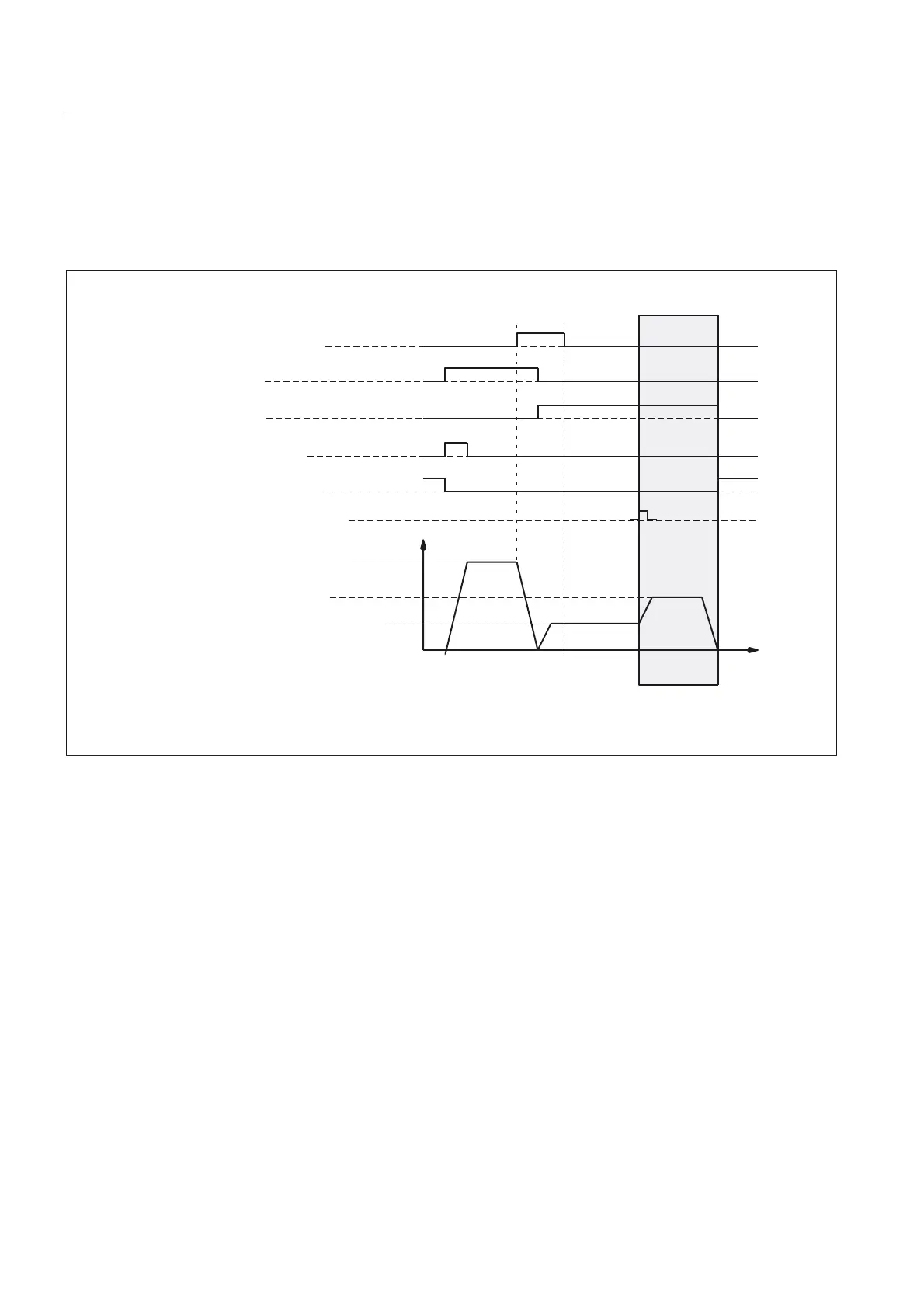
Phase 3: Graphic representation
,6'HFHOHUDWLRQRIUHIHUHQFHSRLQWDSSURDFK
,60RWLRQFRPPDQGSOXV
,60RWLRQFRPPDQGPLQXV
,67UDYHUVLQJNH\SOXVPLQXV
'%'%;DQG
,65HIHUHQFHGV\QFKURQL]HG
'%'%;DQG
=HURPDUNSRVLWLRQPHDVXULQJ
V\VWHP
9HORFLW\
5HIHUHQFHSRLQWDSSURDFKYHORFLW\
5HIHUHQFHSRLQWFUHHSYHORFLW\
5HIHUHQFHSRLQWSRVLWLRQLQJ
YHORFLW\
3KDVH
0'5()3B9(/2B6($5&+B0$5.(5
0'5()3B9(/2B326
0'5()3B9(/2B6($5&+B&$0
'%'%;
'%'%;
'%'%;
W
Fig. 2-8 Phase 3: Traversing to the reference point
Phase 3: Start
At the end of phase 2 the machine axis travels at reference point creep velocity. Therefore,
as soon as phase 2 is completed successfully without an alarm, phase 3 is started without
interruption.
Initial situation
The encoder zero mark has been detected.
 Loading...


