Detailed Description
2.4 Frames
Axis Types, Coordinate Systems, Frames (K2)
2-38 Function Manual, 08/2005 Edition, 6FC5397-0BP10-0BA0
2.4 2.4 Frames
2.4.1 Coordinate axes, zeros and reference points
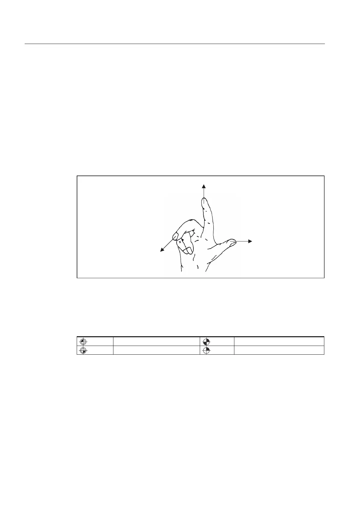
As a rule, a coordinate system is formed of three mutually perpendicular coordinate axes.
The positive directions of the coordinate axes are determined using the right hand rule. The
coordinate system is related to the workpiece and programming takes place independently of
whether the tool or the workpiece is being traversed. When programming, it is always
assumed that the tool traverses relative to the coordinate system of the workpiece, which is
intended to be stationary.
[
\
]
The neutral position of the machine is obtained from the coordinate axes and the
constructive characteristics of the machine. The zero of the coordinate system is obtained by
defining a suitable reference point on the machine in its neutral position.
The position of the coordinate systems (MCS, BCS, BZS, SZS, WCS) is determined by
means of zeros.
M = Machine zero
R = Reference point
W = Workpiece zero
T = Toolholder reference point
 Loading...


