Detailed Description
2.3 Tool cutting edge
Tool Compensation (W1)
Function Manual, 08/2005 Edition, 6FC5397-0BP10-0BA0
2-33
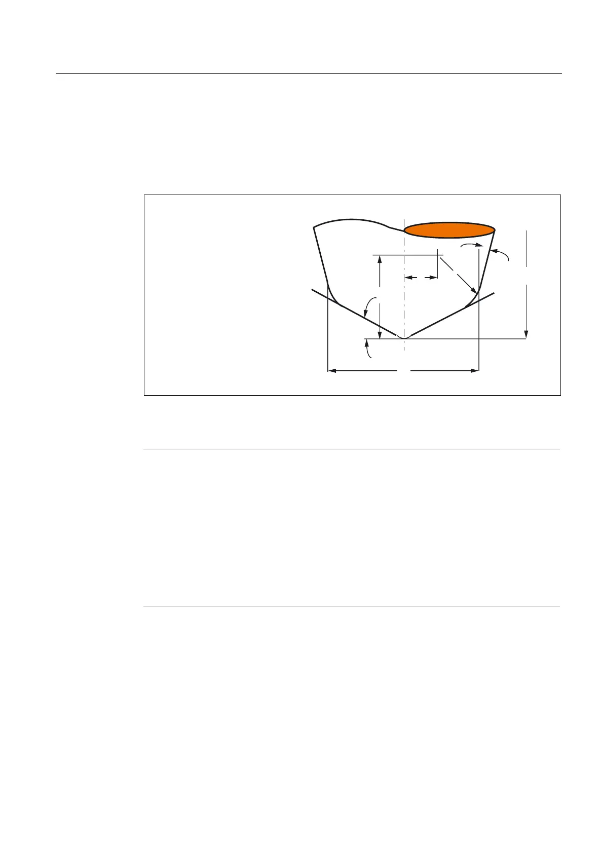
2.3.5 Geometry tool radius compensation (tool parameters 6 to 11)
Tool geometry
Geometry tool radius compensation defines the shape of the tool.
G
K
E
H
D
U
I
KWRROOHQJWK
7RRO3IOHQJWK
7RRO3HOHQJWK
7RRO3GUDGLXV
7RRO3UUDGLXV
7RRO3DDQJOH
7RRO3EDQJOH
Fig. 2-9 Description of the tool geometry
Note
The tool description as given in the figure is required only for 3D face milling.
Otherwise,
on SINUMERIK 840D/810D, only tool parameter 6 (tool radius 1) is used from tool
parameters 6 to 11.
Please refer to the following documentation for information about entering tool shapes
(radius for tool radius compensation) in tool parameters 6 to 11 and how these are
calculated by tool radius compensation in the three geometry axes:
References:
/PA/ Programming Guide, Fundamentals
/FB3/ Description of Functions, Special Functions; 3D Tool Radius Compensation (W5).
 Loading...


