Detailed Description
2.3 Tool cutting edge
Tool Compensation (W1)
Function Manual, 08/2005 Edition, 6FC5397-0BP10-0BA0
2-27
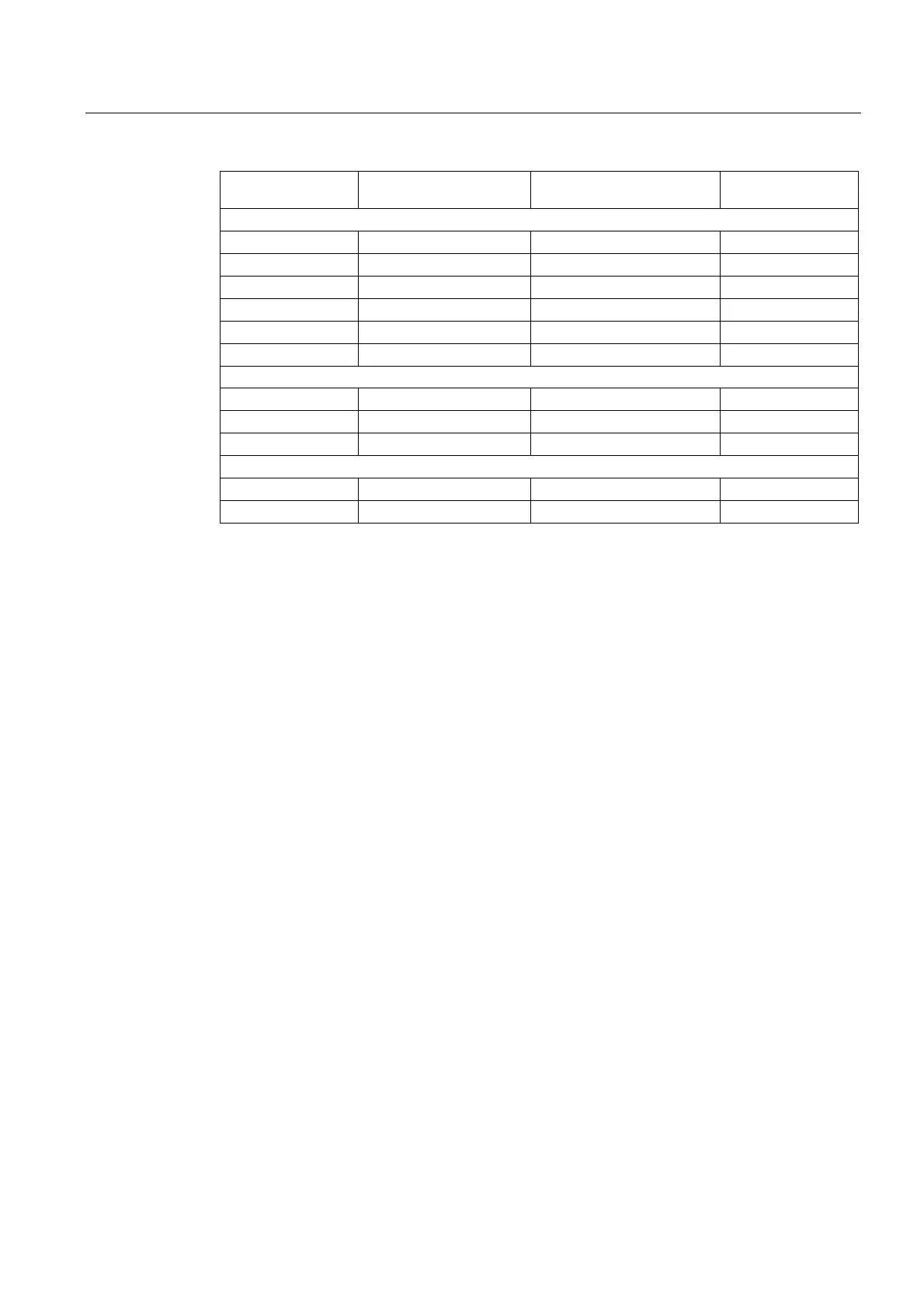
Tool parameter Meaning Note Reserved for
expansions
Wear tool radius compensation
15 Radius 1/Length 1 for 3D face milling
16 Length 2 for 3D face milling
17 Radius 1 for 3D face milling
18 Radius 2 for 3D face milling
19 Angle 1 for 3D face milling
20 Angle 2 for 3D face milling
Tool base dimension/adapter dimension tool length compensation
21 Basic length 1
22 Basic length 2
23 Basic length 3
Technology
24 Undercut angle only for turning tools
25 Reserved
*
*
"Reserved" means that this tool parameter on the 840D/810D is not used (reserved for
expansions).
Milling cutter types 111, 120, 121, 130, 155, 156 and 157 3D are given special treatment for
face milling by evaluating tool parameters (1 - 23).
For more information about the different tool types, see
Subsection 7.7.1 Tool type (tool parameters) and
References:
/FB1/ Description of Functions, Basic Machine; Tool Compensation (W1),
Chapter "Tool type (tool parameters)"
/FB3/ Description of Functions, Special Functions; 3D Tool Radius Compensation (W5)
2.3.2 Tool type (tool parameters)
Meaning
A 3digit number is used to define the tool type. The operator/machine setter/programmer
selects the tool type. This determines further components such as geometry, wear and tool
base dimensions in advance. The tool type has no meaning in the grinding and turning tool
groups. Non-listed numbers are also permitted, in particular with grinding tools (400-499).
 Loading...


