Supplementary conditions
3.2 Output behavior
Auxiliary Function Output to PLC (H2)
3-2 Function Manual, 08/2005 Edition, 6FC5397-0BP10-0BA0
3.2 3.2 Output behavior
Thread cutting
During active thread cutting G33, G34, and G35, the following output behavior is always
active for the spindle-specific auxiliary functions:
• M3 (spindle right)
• M4 (spindle left):
• Output duration one OB40 cycle (quick acknowledgment)
• Output during motion
The spindle-specific auxiliary function M5 (spindle stop) is always output at the end of the
block. The part program block that contains M5 always ends with an exact stop, even if
continuous-path mode is active.
Synchronized actions
With output auxiliary functions from synchronized actions, the parameterized output behavior
is ignored except for the following parameters:
• Bit0: Output duration one OB1 cycle (normal acknowledgment)
• Bit1: Output duration one OB40 cycle (quick acknowledgment)
Auxiliary functions: M17 or M2/M30 (end of subroutine)
Only one auxiliary function in a part program block
If one of the auxiliary functions M17, M2, or M30 is programmed as the only auxiliary
function in a part program block and an axis is still in motion, the auxiliary function is not
output to the PLC until after the axis has stopped.
Overlaying parameterized output behavior
The parmeterized output behavior of auxiliary functions: M17 or M2/M30 is overlaid by the
output behavior defined in the following machine data:
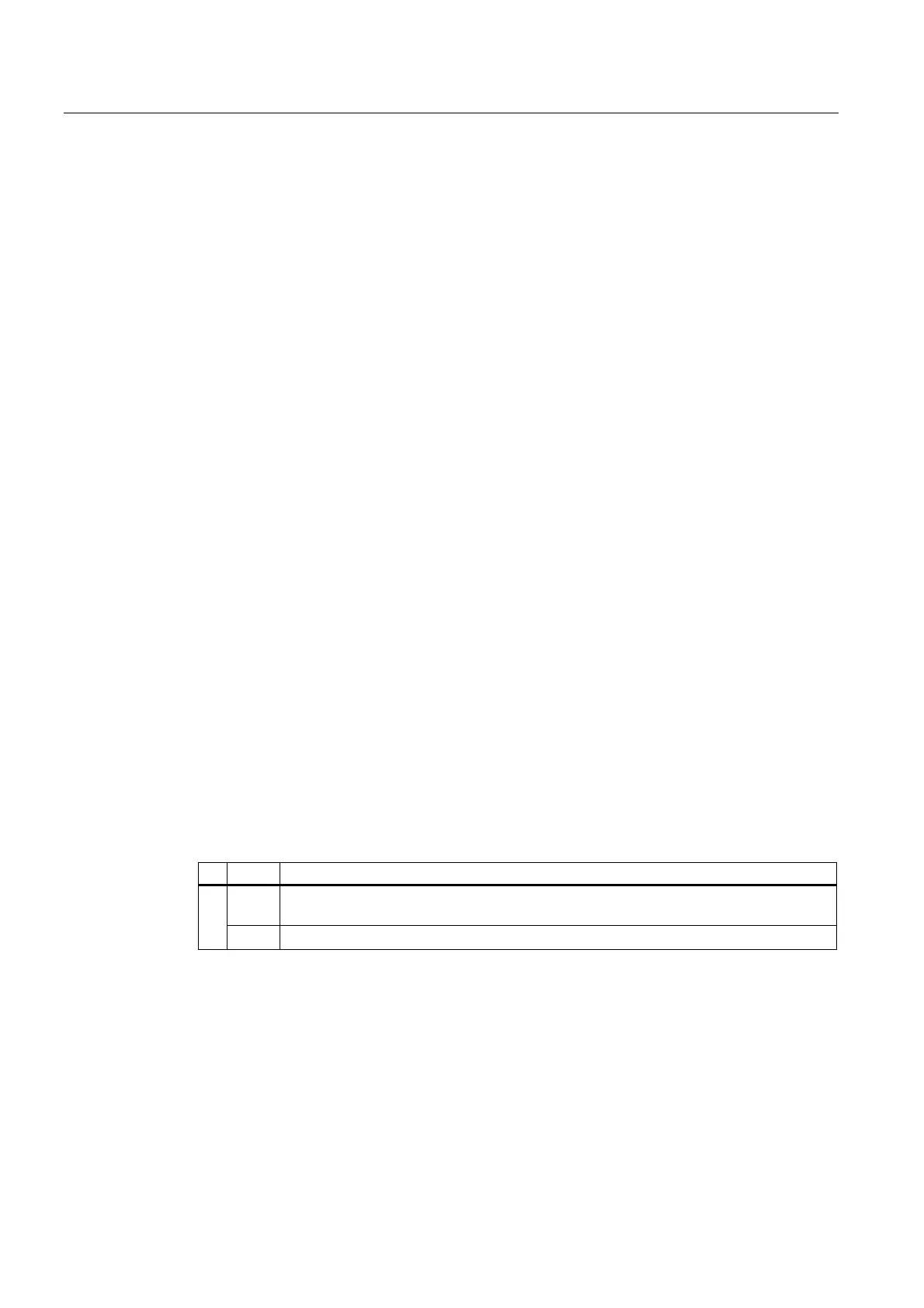
MD20800 $MC_SPF_END_TO_VDI, Bit 0 (end of subroutine/stop to PLC)
Bit Value Meaning
0 The auxiliary functions M17 or M2/M30 (end of subroutine) are not output to the PLC.
Continuous-path mode is not interrupted at the end of the subroutine
0
1 The auxiliary functions M17 or M2/M30 (end of subroutine) are output to the PLC.


