4.1 Test Run
4-17
Chapter 4 OPERATION
4.1.9 Basic settings of function codes < 4 >
When using "vector control with speed sensor (F42
*
=6)" and combining the inverter with the Fuji motors
(VG motors) exclusively designed for vector control, set the function code data as listed below.
For details on how to modify the function code data, see Chapter 3, Section 3.4.2 "Setting up function
codes Menu #1 “Data Setting”."
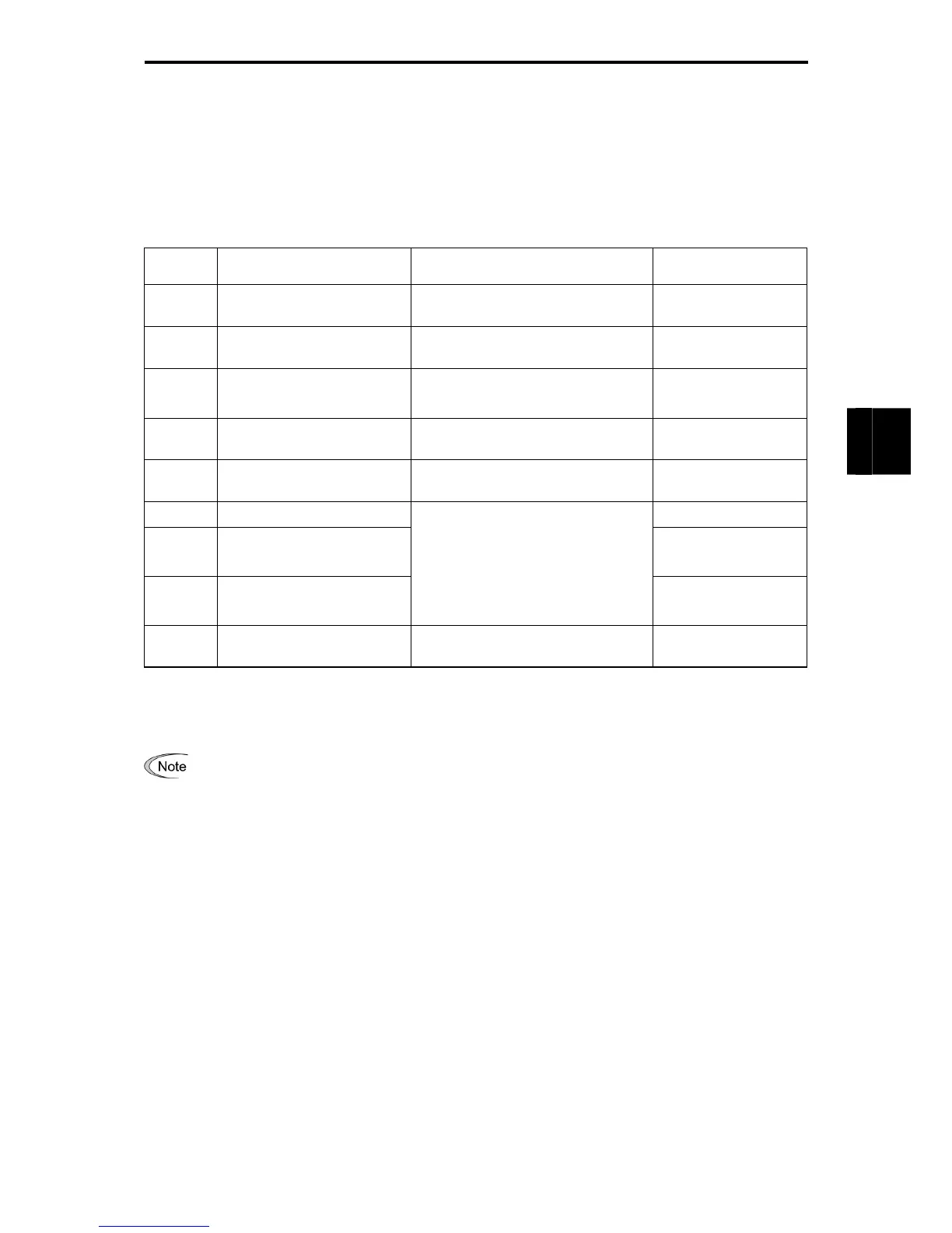
Table 4.1-14
Function
Code
Name Function code data Factory default
p 99
*
Motor 1 selection 2: Motor characteristics 2 (VG motor)
0: Motor characteristics
0
p 02
*
Motor 1 (Rated capacity) Capacity of motor connected
Nominal applied motor
capacity
h
26
Thermistor (for motor)
(operation selection)
3: Operation (with NTC connected)
Also switch SW5 on the control PCB.
0: No operation
d 14
Feedback input
Pulse input system
2: 90 degree phase shifted A/B pulse
trains
2: A/B phases
d 15
Feedback input
Encoder pulse resolution
0400
(1024)
0400
(1024)
f 03
*
Maximum frequency 1 60.0 (Hz)
f 07
Acceleration time 1 (Note)
22 kW or less: 6.00 (s)
30 kW or more: 20.00
(s)
f 08
Deceleration time 1 (Note)
Machinery design values
(Note)
For a test-driving of the motor,
increase values so that they are
longer than your machinery design
values. If the specified time is
short, the inverter may not run the
motor properly.
22 kW or less: 6.00 (s)
30 kW or more: 20.00
(s)
f 11
*
Electronic thermal 1 (for motor
protection) (operation level)
0.00 (No operation)
For each inverter
capacity
After the above configuration, initialize motor 1 with the function code (H03 = 2). The function codes F04
*
,
F05
*
, P01
*
, P03
*
, P06
*
to P23
*
, P53
*
to P56
*
, and H46 for the motor parameters required for vector control
are automatically set.
Be very careful when changing the P02
*
data because doing so automatically updates the data of the
function codes F04
*
, F05
*
, P03
*
, P06
*
to P23
*
, P53
*
to P56
*
, and H46.

 Loading...


