5.4 Details of Function Codes
5-249
Details of
Function Codes
F codes
E codes
C codes
P codes
H codes
A codes
b codes
r codes
J codes
d70 to d99
U00 to U91
y codes
Chapter 5 Function Code
5.4.9 U codes (Application functions 3)
U00
U01 to U50
U71 to U75
U81 to U85
U91
Customizable Logic (Operation Selection)
Customizable Logic: Step 1 to 10 (Operation Setting)
Customizable Logic Output Signal 1 to 5 (Output Selection)
Customizable Logic Output Signal 1 to 5 (Function Selection)
Customizable Logic Timer Monitor (Step Selection)
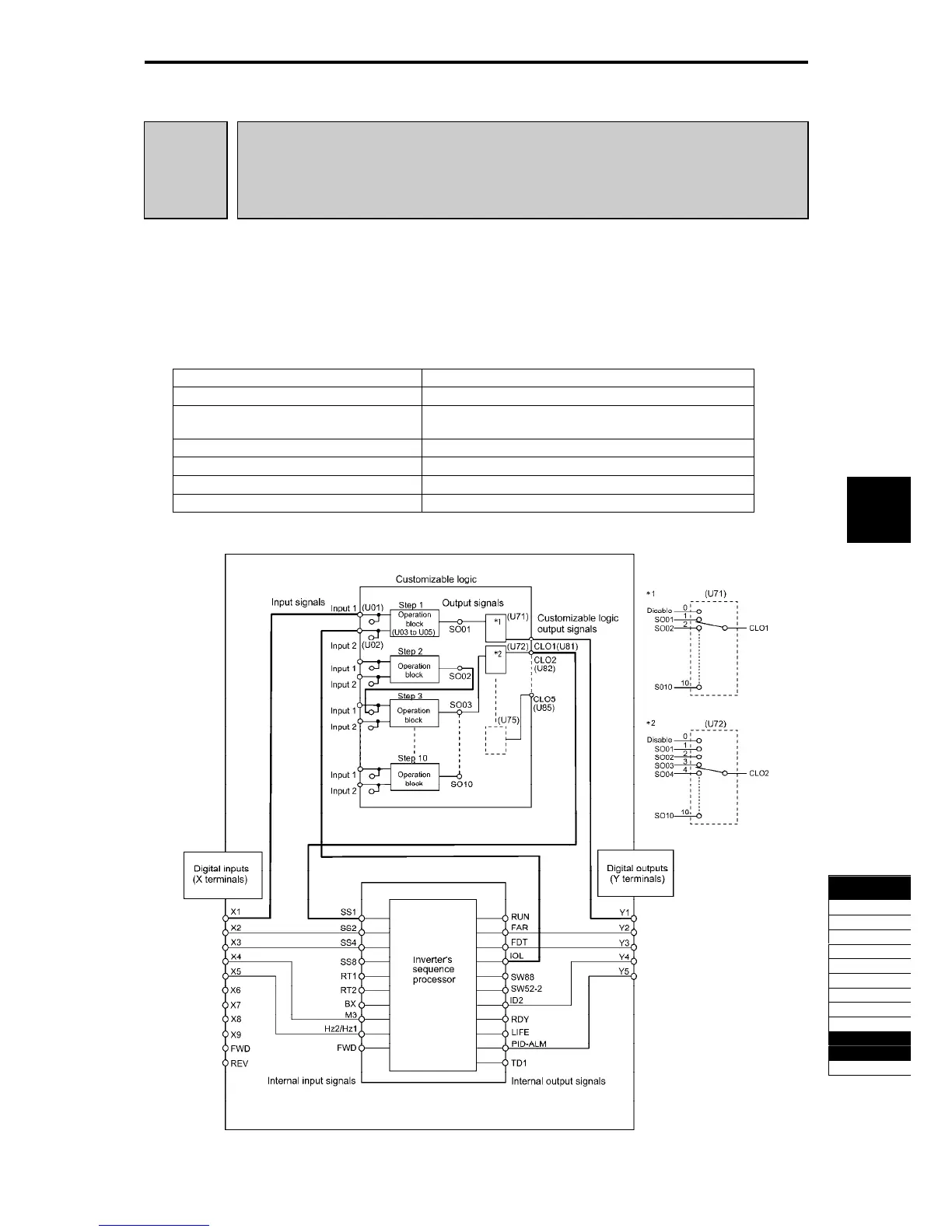
The customizable logic function allows the user to form a logic circuit for digital input/output signals,
customize those signals arbitrarily, and configure a simple relay sequence inside the inverter.
In a customizable logic, one step (component) is composed of 2 inputs and 1 output + logical operation
(including timer) and a total of ten steps can be used to configure a sequence.
Specifications
Table 5.4-175
Item Specifications
Input signal 2 inputs
Operation block Logical operation, counter, etc.: 13 types
Timer: 5 types
Output Signal 1 output
Number of steps 10 steps
Customizable logic output signal 5 outputs
Customizable logic processing time 2 ms (See page 5-256 " Notes for Usage (4).")
Block diagram
Fig. 5.4-126

 Loading...


