2.2 Wiring
2-20
[3] Notes on control circuit wiring
For FRN75G1S-2J, FRN90G1S-2J, and FRN132G1S-4J to FRN630G1S-4J
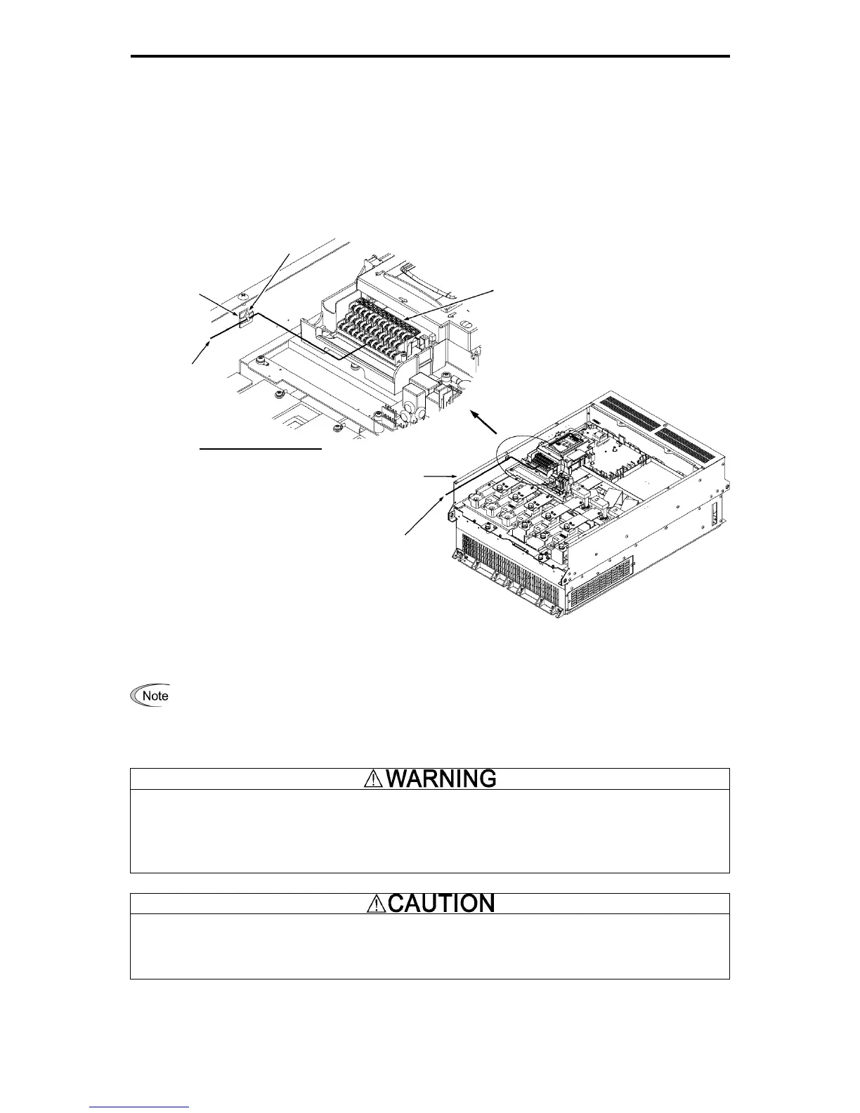
(1) As shown in Figure 2.2-16, run the wires along the left-side panel of the inverter.
(2) Secure the wires to the wire fixing holders with cable ties (wire bands, etc.).
The cable ties should be max. 3.8 mm in width and max. 1.5 mm in thickness.
Figure 2.2-16 Control Circuit Wiring Layout and Secured Position
• Route the wiring of the control circuit terminals as far from the wiring of the main circuit as possible.
Otherwise electric noise may cause malfunctions.
• Fix the control circuit wires with a cable tie inside the inverter to keep them away from the live parts o
the main circuit (such as the terminal block of the main circuit).
Generally, the insulation for control signal wires are not enhanced. When the control signal wires come into
direct contact with the main circuit live section, the insulation cover may be damaged. High voltage of the main
circuit may be applied on the control signal wires, so exercise caution such that the main circuit live sections do
not contact the control signal wires.
Risk of accidents and risk of electric shock exist.
Noise is generated by the
inverter, motor, and wiring.
Exercise caution to prevent malfunction of peripheral sensors and instruments.
Risk of accidents exists.
The connection method differs for the control circuit terminals depending on the functional code setting matching
the purpose of inverter operation.
Properly wire such that the impact of noise generated by the main circuit wiring is reduced.
Control circuit
wiring
Control circuit
wiring
Wire fixing holder
Cable tie
Control circuit
terminal block
Detail drawing of A part

 Loading...


