App. C Effect on Insulation of General-purpose Motors Driven with 400 V Class Inverters
A-17
App.
App. C Effect on Insulation of General-purpose Motors Driven with 400 V
Class Inverters
This document provides you with a summary of the Technical Document of
the Japan Electrical Manufacturers' Association (JEMA) (March, 1995).
Preface
When an inverter drives a motor, surge voltages generated by switching the inverter elements are
superimposed on the inverter output voltage and applied to the motor terminals. If the surge voltages are
too high, they may have an effect on the motor insulation and some cases have resulted in damage.
For preventing such cases this document describes the generating mechanism of the surge voltages and
countermeasures against them.
Refer to A.2 [1] "Inverter noise" for details of the principle of inverter operation.
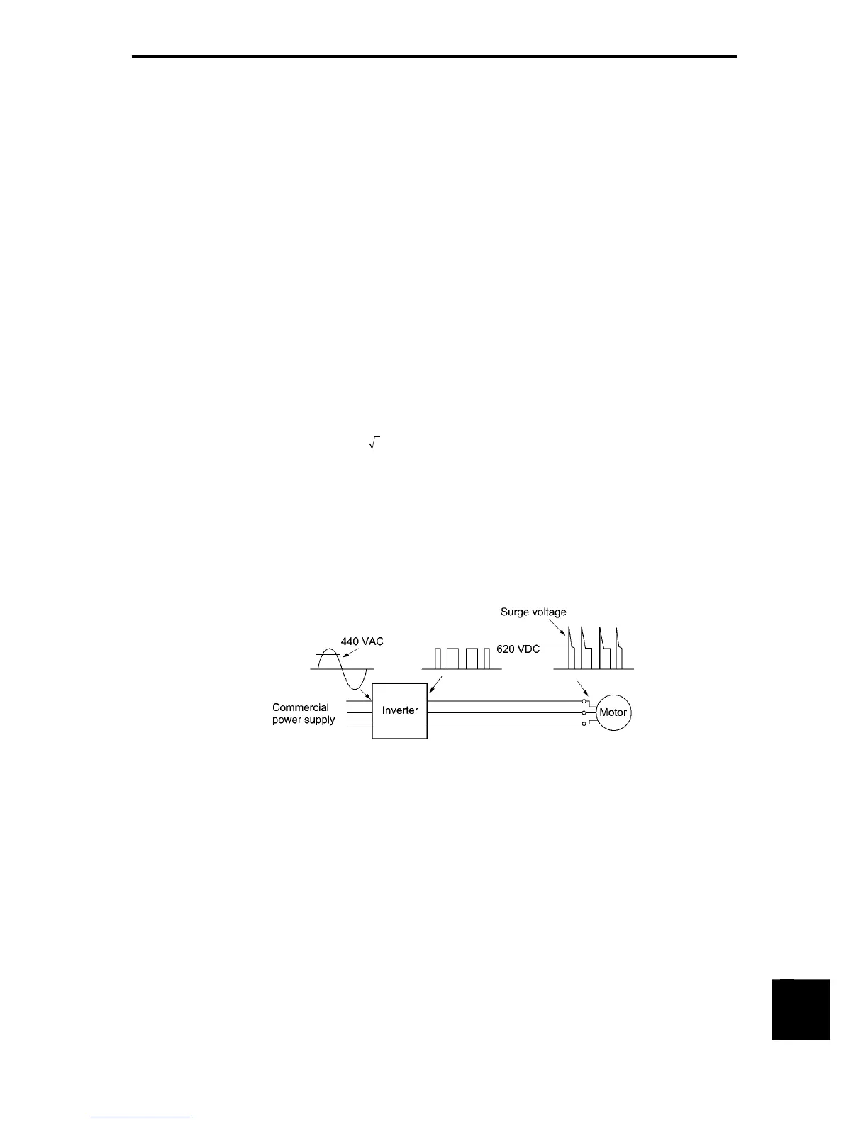
C.1 Generating mechanism of surge voltages
As the inverter rectifies a commercial power source voltage and smooths into a DC voltage, the magnitude
E of the DC voltage becomes about
2 times that of the source voltage (about 620 V in case of an input
voltage of 440 VAC). The peak value of the output voltage is usually close to this DC voltage value.
But, as there exists inductance (L) and stray capacitance (C) in wiring between the inverter and the motor,
the voltage variation due to switching the inverter elements causes a surge voltage originating in LC
resonance and results in the addition of high voltage to the motor terminals. (Refer to Figure C-1.)
This voltage sometimes reaches up to about twice that of the inverter DC voltage (620 V x 2 =
approximately 1,200 V) depending on a switching speed of the inverter elements and wiring conditions.
Figure C-1 Voltage Waveform of Individual Portions
A measured example in Figure C-2 illustrates the relation of a peak value of the motor terminal voltage with
a wiring length between the inverter and the motor.
From this it can be confirmed that the peak value of the motor terminal voltage ascends as the wiring length
increases and becomes saturated at about twice the inverter DC voltage.
The shorter a pulse rise time becomes, the higher the motor terminal surge voltage rises even in the case of
a short wiring length.

 Loading...


