5.4 Details of Function Codes
5-204
Selection Method of Light alarms object
To set and display the light alarm factors in hexadecimal format, each light alarm factor has been assigned
to bits 0 to 15 as listed in Tables 5.4-138 and 5.4-139. Set the bit that corresponds to the desired light alarm
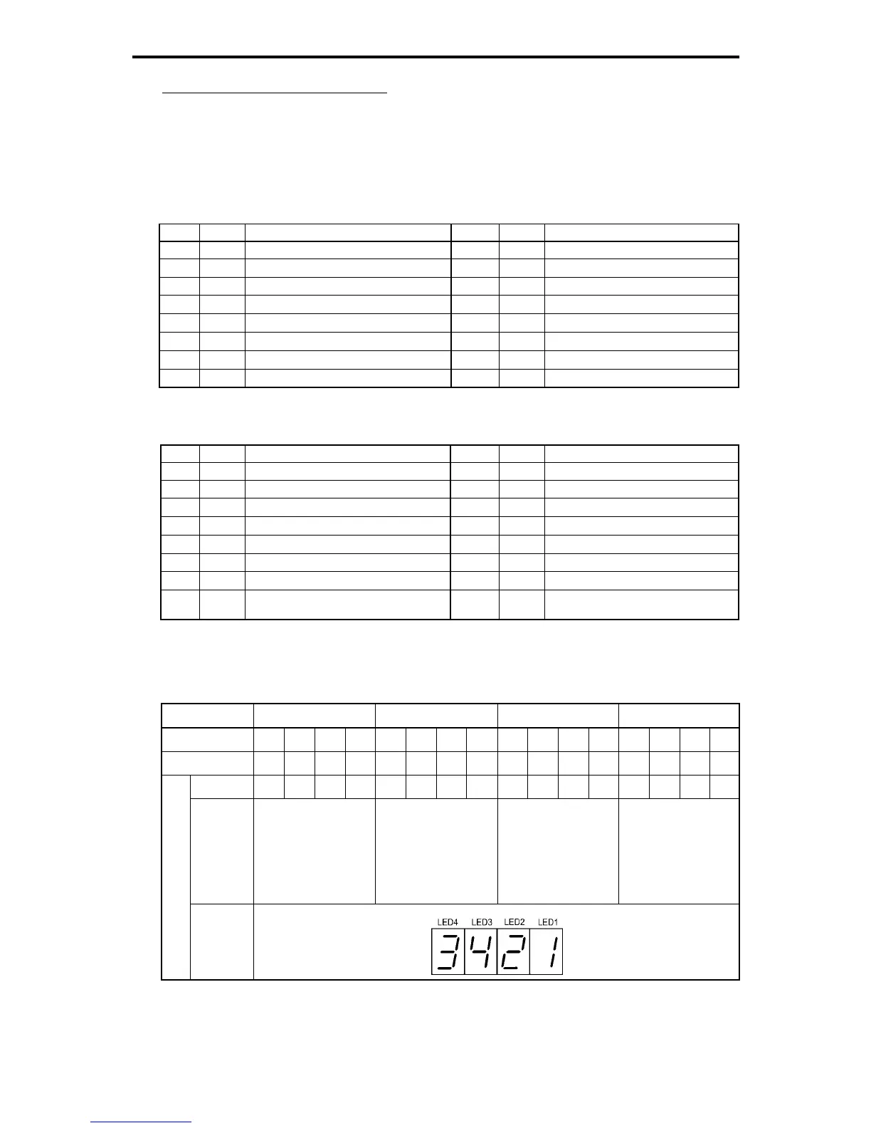
factor to "1." Table 5.4-140 shows the relationship between each of the light alarm factor assignments and
the LED monitor display.
Table 5.4-141 gives the conversion table from 4-bit binary to hexadecimal.
Table 5.4-138 H81 Light Alarm Selection 1, Bit Assignment of Selectable Factors
Bit Code Contents Bit Code Contents
15 - - 7
0l3
Motor 3 overload
14 - - 6
0l2
Motor 2 overload
13
erp
RS-485 communications error (COM port 2) 5
0l1
Motor 1 overload
12
er8
RS-485 communications error (COM port 1) 4
dbh
Braking resistor overheat
11
er5
Option error 3 - -
10
er4
Option communications error 2
0h3
Inverter internal overheat
9 - - 1
0h2
External alarm
8
0l4
Motor 4 overload 0
0h1
Cooling fin overheat
Table 5.4-139 H82 Light Alarm Selection 2, Bit Assignment of Selectable Factors
Bit Code Contents Bit Code Contents
15 - - 7
lif
service life warning
14 - - 6
0h
Cooling fin overheat warning
13
cnT
Machinery life (Number of startups) 5
0l
Motor overload early warning
12
rTe
Inverter life (Cumulative motor run time) 4
fal
DC fan lock detection
11
pTc
Thermistor detection (PTC) 3
cof
PID feedback wire break detection
10
uTl
Low torque output 2
ero
Positioning deviation over
9
pid
PID alarm 1 - -
8
ref
Command loss 0
ere
Speed mismatch or excessive speed
deviation
Table 5.4-140 Display of Light Alarm Factor
(Ex.) H81 "RS-485 communication error (communication port 2)", "RS-485 communication error (communication
port 1)", "Option communication error," "Motor 1 overload," "Cooling fin overheat" is selected
LED No. LED4 LED3 LED2 LED1
Bit 15 14 13 12 11 10 9 8 7 6 5 4 3 2 1 0
Code - -
erp er8 er5 er4
-

 Loading...


