11.4 Option
11-84
[10] Digital output interface card (OPC-G1-DO)
The digital output interface card has eight transistor output terminals (switchable between SINK and
SOURCE). Mounting this interface card on the FRENIC-MEGA enables the user to monitor the output
frequency and other items with binary code (8 bits).
Applicable ports
This interface card can be connected to any one of the three option connection ports (A-, B-, and C-ports)
on the FRENIC-MEGA.
Applicable ROM version
This interface card is applicable to inverters with a ROM version G1S10500 or later.
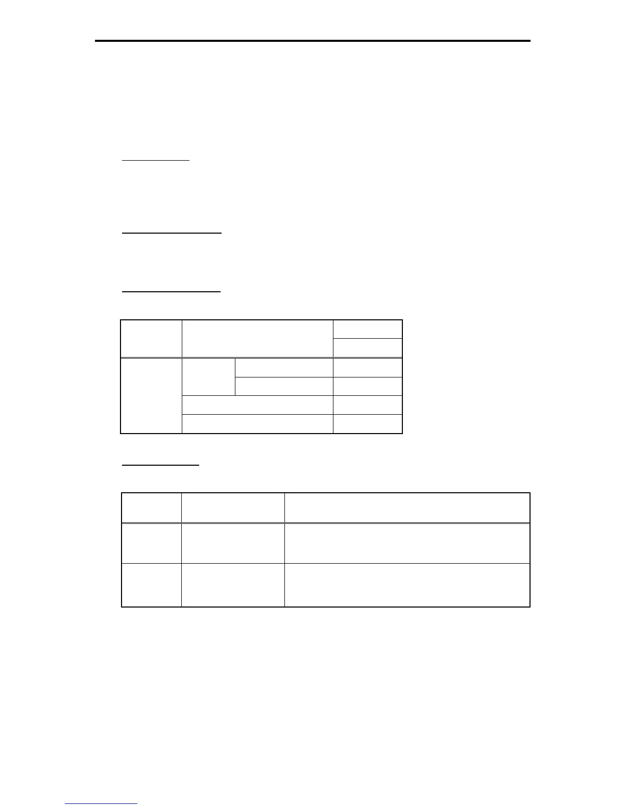
Electrical specifications
Table 11.4-55
Specifications
Terminal
Signal
Item
Max.
ON level 2 V
Operating
voltage
OFF level 27 V
Operating current at ON 50 mA
[O1] to [O8]
Leakage current at OFF 0.1 mA
Terminal functions
Table 11.4-56
Terminal
Signal
Name Functions
[O1] to [O8] Transistor output 1 to 8
These digital terminals output various status signals (e.g.,
output frequency, output current) specified by function code
o21 as an 8-bit parallel signal.
[M2]
Transistor output common
Common terminal for transistor output signals.
This terminal is electrically isolated from terminals [CM], [11],
and [CMY] of the inverter.

 Loading...


